Worktable equipment for machining

A technology of mechanical processing and workbench, which is applied in the direction of metal processing equipment, metal processing machinery parts, manufacturing tools, etc., can solve problems such as difficult to change, unable to process different workpiece adjustments, difficult to popularize and apply, etc.

Pending Publication Date: 2021-05-07
罗福祥
View PDF5 Cites 1 Cited by
  • Summary
  • Abstract
  • Description
  • Claims
  • Application Information

AI Technical Summary

Problems solved by technology

[0003] The existing workbench equipment for mechanical processing has the problem that the processing method is relatively single, and it cannot

Method used


Image

  • Worktable equipment for machining
  • Worktable equipment for machining
  • Worktable equipment for machining

Examples


Embodiment 1

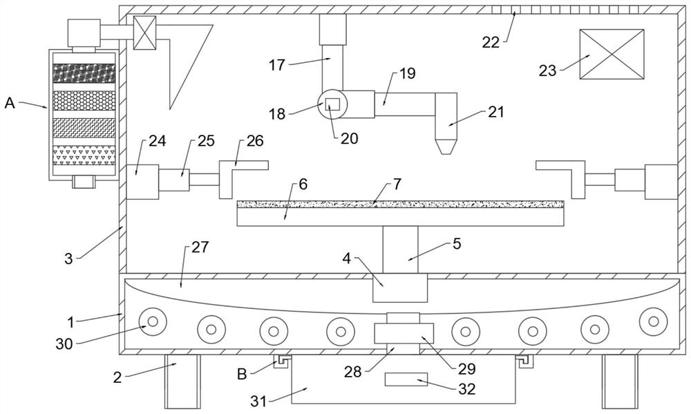
[0031]SeeFigure 1 ~ 3 A mechanical processing table device, including a base 1, and a support leg 2 is provided below, the base 1 is fixed, and the discharge dust cover 3 is fixed, and the base 1 is provided with a rotary electric machine 4. The rotary electric machine 4 is disposed at the center position of the base 1, and the output end of the rotary motor 4 is fixedly coupled to the rotating shaft 5, the rotating shaft 5 away from one end of the rotary electric machine 4 fixed to the processing backplane 6, the drop in dust. A first electric telescopic rod 17 is provided on the cover 3, the first electric telescopic rod 17, away from one end of the dropping dust cover 3, which is connected to the second electric telescopic rod 19, said The second electric telescoping rod 19 is fixed from one end of the electric rotary shaft 18, and the height of the machining center 21 can be effectively adjusted by the first electric telescopic rod 17, the electric rotary shaft 18, the electric ...

Embodiment 2

[0039]SeeFigure 1 ~ 5A mechanical processing table device, including base 1, further comprising mounting lever 35, pulley 36, support block 37, threaded through hole 38, rotating handle 39, threaded column 40, stop block 41, and anti-slip pad 42, Next, a support leg 2 is provided below, and a rotating dust cover 3 is fixed to the base 1, and a rotating electric machine 4 is provided, the rotating motor 4 is disposed at the center position of the base 1, the The output end of the rotary electric machine 4 fixed to the rotating shaft 5, the rotating shaft 5 away from one end of the rotary electric machine 4 to fix the workpiece 6, and a first electric telescopic rod 17 is provided on the prolonel dust cover 3, and the first An electric telescopic rod 17 is disposed at one end of the dropping dust cover 3, which is connected to the second electric telescopic rod 19, the second electric telescopic rod 19 away from one end of the electric spindle 18 fixed connection processing. The cente...


PUM


Abstract

The invention discloses worktable equipment for machining, and belongs to the technical field of machining equipment. The problem that an existing machining table is poor in machining effect is solved. According to the technical key points, the worktable equipment comprises a base, and supporting legs are symmetrically arranged below the base; a noise reduction dust cover is fixedly connected to the base; a rotating motor is arranged in the base, and located in the center of the base, and the output end of the rotating motor is fixedly connected with a rotating shaft; the end, away from the rotating motor, of the rotating shaft is fixedly connected with a machining bottom plate, and a first electric telescopic rod is arranged on the noise reduction dust cover; an electric rotating shaft is arranged at the end, away from the noise reduction dust cover, of the first electric telescopic rod, and connected with a second electric telescopic rod; and the end, away from the electric rotating shaft, of the second electric telescopic rod is fixedly connected with a machining center. The worktable equipment has the advantage of a good machining effect.

Description

Technical field[0001]The present invention relates to the technical field of mechanical processing equipment, and in particular, to a workstable device for machining.Background technique[0002]Machine is to help people reduce the difficult or labor-saving tools, such as chopsticks, brooms, and tweezers, can be called mechanical, they are simple machinery. The complex mechanical is composed of two or more simple mechanical components. These more complex machinery are usually called machines. From the perspective of structures and sports, there is no difference between the agency and machines, which is generally known as machinery, generally, mechanical is to reduce the difficulty or effortless tools, like chopsticks, brooms, and tweezers. It is called mechanical, they are simple machinery. The complex mechanical is composed of two or more simple mechanical components. These more complex machinery are usually called machines.[0003]The existing mechanical processing workbench equipment ...

Claims


Application Information

Patent Timeline
IPC IPC(8): B23Q1/01B23Q1/25B23Q11/00B23Q11/08B01D46/00B01D53/04B01D53/26
CPCB23Q1/015B23Q1/25B23Q11/0042B23Q11/08B01D53/04B01D53/26B01D2253/102B01D46/64
Inventor 罗福祥
Owner 罗福祥
Why Eureka
Try Eureka