
Method for annealing plates through coiled material vertical vacuum annealing furnace

A technology of vacuum annealing furnace and plate, applied in the direction of furnace, furnace type, heat treatment furnace, etc., to achieve the effect of ensuring flatness, ensuring safe production, and ensuring uniform transfer

Active Publication Date: 2021-05-07
西安西部新锆科技股份有限公司
View PDF7 Cites 0 Cited by
  • Summary
  • Abstract
  • Description
  • Claims
  • Application Information

AI Technical Summary

Problems solved by technology

According to the charging method, heating and heat radiation mode, and the specification and shape of zirconium materials, the horizontal furnace is only suitable for annealing of plates, and the vertical furnace is only suitable for annealing of coils. There is a big difference between the two.

Method used


Image

  • Method for annealing plates through coiled material vertical vacuum annealing furnace
  • Method for annealing plates through coiled material vertical vacuum annealing furnace
  • Method for annealing plates through coiled material vertical vacuum annealing furnace

Examples


Embodiment 1

[0043] This embodiment includes the following steps:

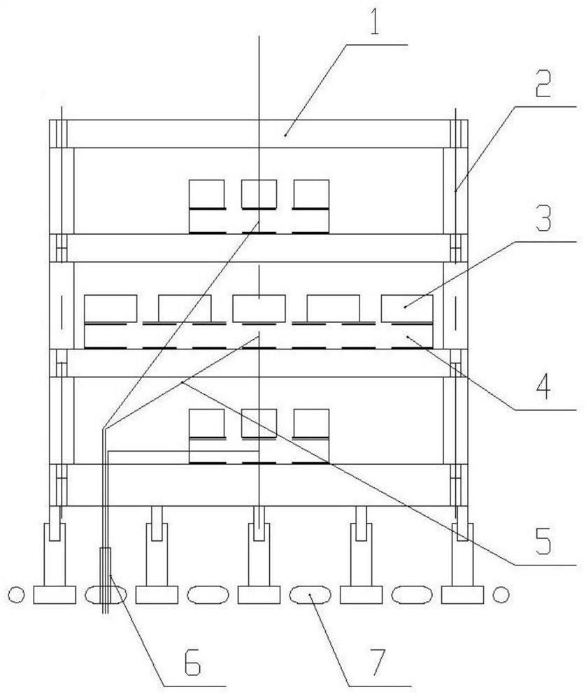
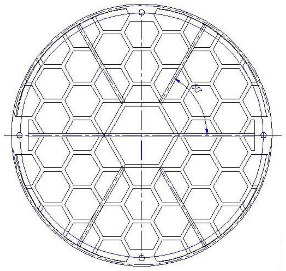
[0044] Step 1. According to the uniform temperature zone specifications of the coil vertical vacuum annealing furnace chamber, the characteristics of the heating method and the overall layout of the radiation heating zone, design and manufacture a special tooling suitable for the coil vertical vacuum annealing furnace chamber; the coil The standard diameter×height of the uniform temperature zone of the vertical vacuum annealing furnace is 1200mm×1200mm. The heating method is characterized by the combination of lateral radiation heating and top and bottom auxiliary heating. The overall layout of the radiation heating zone is a vertical cylinder; the special The three layers of detachable trays in the tooling are all grid structures, and the bottom of each layer of trays is provided with grooves, and support columns are arranged between adjacent trays, and the tops of the support columns are in contact with the adjacent trays...

Embodiment 2

[0052] The difference between this embodiment and Embodiment 1 is that: the height of the support column in step 1 is 150mm; the temperature of the vacuum annealing process in step 5 is 550°C, and the holding time is 1.5h; the heating rate is set to 2 in step 6. ℃ / min, set the output power difference as 55%.

Embodiment 3

[0054] The difference between this example and Example 1 is that the height of the support column in step 1 is 350mm; the temperature of the vacuum annealing process in step 5 is 620°C, and the holding time is 3h; the heating rate is set at 8°C in step 6 / min, set the output power difference as 35%.


PUM

PropertyMeasurementUnit
Heightaaaaaaaaaa
Thicknessaaaaaaaaaa
Widthaaaaaaaaaa

Abstract

The invention discloses a method for annealing plates through a coiled material vertical vacuum annealing furnace. The method comprises the steps that firstly, a special tool of a furnace chamber of the coiled material vertical vacuum annealing furnace is designed and manufactured; secondly, raw material plates are split and cleaned to obtain the plates; thirdly, the plates are stacked in the first trays of the special tool, the middle positions are reserved, and then lining plates and pressing blocks are laid; fourthly, charging is completed according to the charging technology in the third step, and temperature measuring workpiece pairs are arranged in the middles of all plate layers correspondingly; fifthly, a vacuum annealing process is designed, and the vacuum annealing process is input into an operation control system for execution; and sixthly, the heating rate is set, the output power is adjusted, and vacuum annealing is completed. The special tool for the coiled material vertical vacuum annealing furnace is designed, the charging mode is improved, the heating parameters are adjusted, the plates are loaded into the vertical space, heat is evenly transmitted to the plates, the annealing temperature consistency of the plates on different layers is improved, and annealing of the coiled material vertical vacuum annealing furnace for the plates is achieved.

Description

technical field [0001] The invention belongs to the technical field of metal material processing, and in particular relates to a method for annealing a plate by using a coiled material vertical vacuum annealing furnace. Background technique [0002] Zirconium alloys are widely used in the nuclear industry due to their low thermal neutron absorption cross section, good corrosion resistance to high temperature water and superheated steam, and good mechanical properties. Zirconium alloy plates used in the nuclear industry have extremely high requirements on their corrosion and other properties, and vacuum annealing is the key to determine the performance of zirconium alloy plates. [0003] The plate horizontal vacuum annealing furnace (hereinafter referred to as "horizontal furnace") adopts a flat charging method, and its heating method is longitudinal heat radiation and heat conduction; while the coil vertical vacuum annealing furnace (hereinafter referred to as "vertical furn...

Claims


Application Information

Patent Timeline
IPC IPC(8): C22F1/18C22F1/02C21D9/00C21D1/26C21D11/00
CPCC21D1/26C21D9/0025C21D9/0081C21D11/00C22F1/02C22F1/186
Inventor 范清松席波涛刘杰崔顺周莹王星王文博李宇力周军
Owner 西安西部新锆科技股份有限公司
Learn More