
Laser annealing device and annealing method thereof

A laser annealing and annealing technology, which is applied in the direction of laser welding equipment, electrical components, circuits, etc., can solve the problems that the surface of the silicon wafer exceeds, affects the consistency of annealing temperature, reduces the photolithography effect and stability of the silicon wafer, and achieves improved annealing. The effect of temperature uniformity

Active Publication Date: 2018-08-17
SHANGHAI MICRO ELECTRONICS EQUIP (GRP) CO LTD
View PDF6 Cites 14 Cited by
  • Summary
  • Abstract
  • Description
  • Claims
  • Application Information

AI Technical Summary

Problems solved by technology

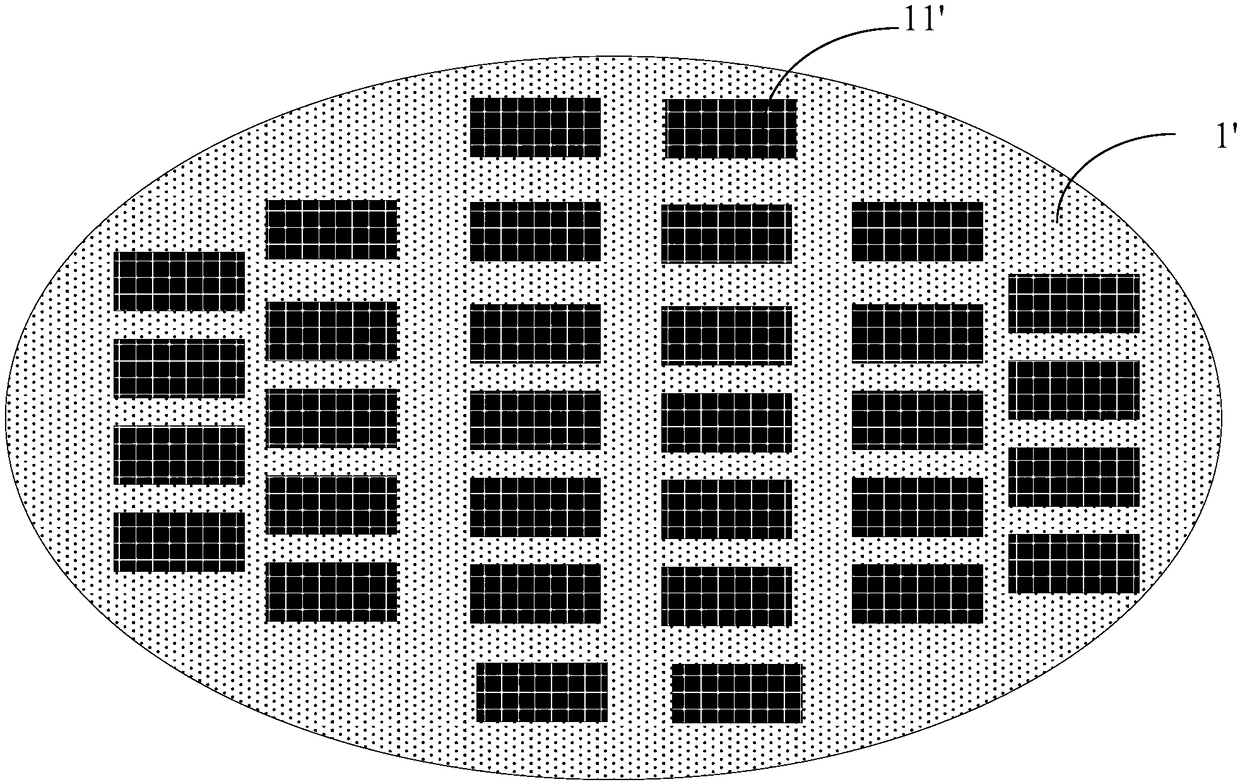
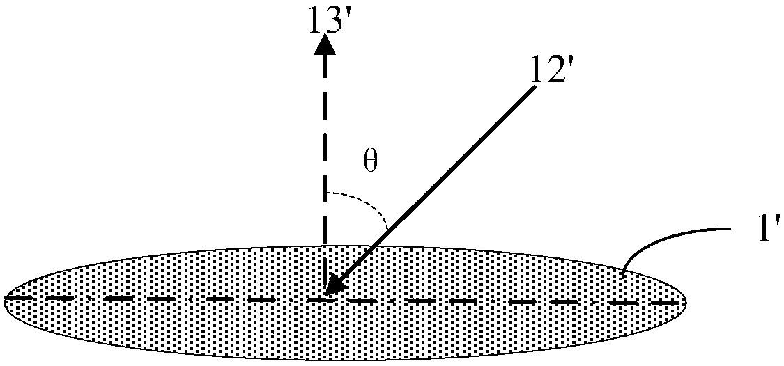
[0007] However, the existing laser annealing technology only uses a laser with one wavelength for annealing, which causes a patterning effect on the silicon wafer, and when the step size of the annealing spot is increased, the surface of the silicon wafer is prone to exceed the focal plane of the spot, which seriously affects the Uniform annealing temperature greatly reduces the photolithographic effect and stability of silicon wafers
In addition, with the improvement of the integration of semiconductor devices, it is required that the chip distribution on the silicon wafer occupies as large an area as possible, and finally the chip is very close to the edge of the silicon wafer, while the annealing spot of the existing laser annealing scans the edge of the silicon wafer. , it will irradiate the workpiece table, causing damage to the parts of the workpiece table

Method used


Image

  • Laser annealing device and annealing method thereof
  • Laser annealing device and annealing method thereof
  • Laser annealing device and annealing method thereof

Examples


Embodiment Construction

[0070] In order to make the purpose and features of the present invention more obvious and understandable, the specific implementation of the present invention will be further described below in conjunction with the accompanying drawings. However, the present invention can be implemented in different forms and should not be limited to the described embodiments.

[0071] Please refer to Figure 4 to Figure 6 , the laser annealing device provided by the present invention mainly includes: the main frame of the equipment 000, the laser light source system 001 emitting the preheating laser beam 005 and the annealing laser beam 006, and the active shock absorption platform 002 for carrying the workpiece 004 to be annealed (such as 003, workpiece protection ring 010, ambient air filter 011, purification gas purging device 012, workpiece preheating platform 013, workpiece cooling platform 014, laser adjustment system 015 , slide stage movement system 016, measurement system and centra...


PUM


Abstract

The invention provides a laser annealing device and an annealing method thereof. The laser annealing device comprises a sheet carrying table and a laser light source system mainly formed by a preheating laser light source system and an annealing optical system, a laser adjustment system, a measurement system, a sheet carrying table moving system and a central control system. By adopting the laserannealing device and the annealing method thereof, adjustability of an incident angle between an incident beam and the surface of a workpiece to be annealed within a certain range and movement of a light spot position can be realized; by compensating adjustment of the laser adjustment system through adjustment of the sheet carrying table, the annealing surface of the workpiece to be annealed needsto always keep the incident beam in a public focal plane, and the consistence of annealing energy is ensured; a measurement result of the measurement system can be controlled by the central control system to be fed back to adjustment of the sheet carrying table moving system or the laser adjustment system, so that work in the annealing process is in an optimal state; and in addition, by arranginga workpiece protective ring on the sheet carrying table, the sheet carrying table can be effectively avoided from being damaged by an annealing laser beam, and a maximum annealing area can also be acquired.

Description

technical field [0001] The invention relates to the field of laser annealing, in particular to a laser annealing device and an annealing method thereof. Background technique [0002] Driven by Moore's Law, the chip manufacturing industry has experienced rapid development in the past few decades. This continued rapid development stems from the continued shrinking of chip sizes. Correspondingly, this smaller size poses increasingly higher difficulties and challenges to the chip manufacturing process. The traditional rapid thermal annealing method for silicon wafers has been difficult to meet the requirements of 14nm and higher nodes. New alternative annealing techniques are being intensively investigated. [0003] Due to the development of laser application technology in recent years, laser annealing technology has shown good application prospects. Compared with traditional annealing, laser annealing has a small thermal budget and high activation efficiency, which can grea...

Claims


Application Information

Patent Timeline
Patent Type & Authority Applications(China)
IPC IPC(8): B23K26/00H01L21/268H01L21/324
CPCB23K26/00H01L21/268H01L21/324
Inventor 罗闻周畅徐建旭
Owner SHANGHAI MICRO ELECTRONICS EQUIP (GRP) CO LTD
Learn More