Multi-head embroidery machine shuttle box assembly with thread buckling mechanism, and embroidery machine

An embroidery machine and shuttle box technology, applied in the field of embroidery equipment, can solve problems such as small driving force

Inactive Publication Date: 2021-05-07
ZHEJIANG XINSHENG SEWING EQUIP
View PDF8 Cites 0 Cited by
  • Summary
  • Abstract
  • Description
  • Claims
  • Application Information

AI Technical Summary

Problems solved by technology

However, the disadvantage of using electromagnetic drive is that the driving force is...

Method used


Image

  • Multi-head embroidery machine shuttle box assembly with thread buckling mechanism, and embroidery machine
  • Multi-head embroidery machine shuttle box assembly with thread buckling mechanism, and embroidery machine

Examples


Embodiment 1

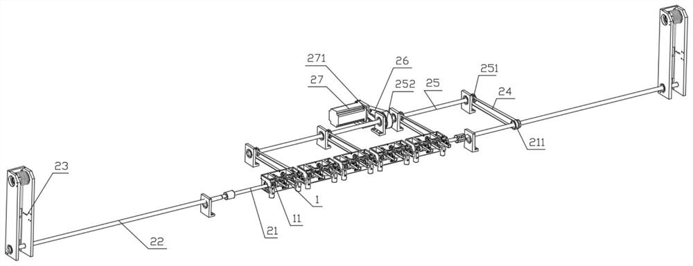
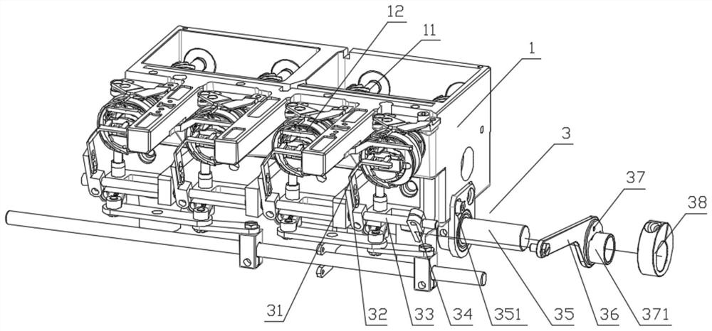
[0029] Such as figure 1 with figure 2 As shown, a multi-head embroidery machine shuttle box assembly with a hook thread mechanism includes a plurality of shuttle boxes 1 arranged side by side, the shuttle box is provided with a rotary hook shaft 11 and a rotary hook 12 connected to the rotary hook shaft 11, It also includes a multi-head rotary hook lower shaft drive mechanism 2 and a wire thread mechanism 3.

[0030] Such as figure 1 The shown multi-head rotary hook lower shaft drive mechanism 2 includes a lower shaft that passes through the plurality of shuttle boxes transversely, the lower shaft is connected to the rotary hook shaft in transmission, and the two ends of the lower shaft correspond to the two upper and lower shafts. The transmission box 23 is transmission connected. The drive mechanism for the lower shaft of the multi-head rotary hook also includes an auxiliary shaft 25 arranged parallel to the lower shaft. The auxiliary shaft 25 is driven by an auxiliary s...

Embodiment approach

[0031] As an implementation, the transmission assembly includes the lower shaft driving pulley 251 installed on the auxiliary shaft, the lower shaft driven pulley 211 installed on the lower shaft, and the lower shaft driving pulley and the lower shaft driven pulley. The first drive belt 24 .

[0032] Further, the motor shaft of the auxiliary shaft motor 27 is connected with the auxiliary shaft driving pulley 271, the auxiliary shaft driven pulley 252 is installed on the auxiliary shaft 25, the auxiliary shaft driving pulley 271 and the auxiliary shaft driven The second transmission belt 26 is connected between the pulleys 252 .

[0033] Preferably, the transmission belt 24 is a timing belt, and the lower shaft driving pulley 251 , the lower shaft driven pulley 211 , the auxiliary shaft driving pulley 271 and the auxiliary shaft driven pulley 252 are all timing pulleys. The lower shaft driving pulley and the lower shaft driven pulley have the same diameter, and the auxiliary s...

Embodiment 2

[0040] An embroidery machine includes the above-mentioned multi-head embroidery machine shuttle box assembly with a thread clamping mechanism.


PUM


Abstract

The invention discloses a multi-head embroidery machine shuttle box assembly with a thread buckling mechanism and an embroidery machine. The multi-head embroidery machine shuttle box assembly comprises a plurality of shuttle boxes arranged side by side, a multi-head rotating shuttle lower shaft driving mechanism and the thread buckling mechanism, wherein the multi-head rotating shuttle lower shaft driving mechanism comprises a lower shaft and an auxiliary shaft arranged in parallel with the lower shaft, two ends of the lower shaft are correspondingly in transmission connection with the two up-down shaft transmission boxes, the auxiliary shaft is driven by an auxiliary shaft motor, at least one transmission assembly synchronously driving the lower shaft to rotate with the up-down shaft transmission boxes is arranged between the auxiliary shaft and the lower shaft in the axial direction, The thread buckling mechanism comprises a thread buckling driving rotating shaft which is rotationally arranged and is parallel to a thread buckling shaft, the thread buckling driving rotating shaft is connected with an eccentric wheel, the eccentric wheel is connected with the thread buckling shaft through a connecting rod, and the thread buckling driving rotating shaft is driven by a thread buckling driving motor or a lower shaft. The rotating amplitude of the lower shaft in the length direction cannot have too large deviation, transmission force is prevented from being attenuated in the direction of the lower shaft, and thread buckling of a plurality of rotating shuttles can be solved.

Description

technical field [0001] The invention relates to embroidery equipment, in particular to a multi-head embroidery machine. Background technique [0002] As the number of embroidery heads on the market continues to increase, the number of hooks also increases. However, the diameter of the lower shaft is relatively small, and the rotation range of the lower shaft along the length direction will deviate. The direction will gradually attenuate, which puts forward higher requirements on the rigidity of the lower shaft. Increasing the diameter of the lower shaft is the best way to improve the rigidity of the lower shaft. However, since the height between the hook and the upper needle plate cannot be changed, Therefore, it is not feasible to increase the diameter of the lower shaft. [0003] At present, most double-needle embroidery machines on the market are non-cutting models. The applicant focuses on developing lace trimming models to reduce labor costs and increase production eff...

Claims


Application Information

Patent Timeline
IPC IPC(8): D05C11/18
CPCD05C11/18
Inventor 王海江田桂郁
Owner ZHEJIANG XINSHENG SEWING EQUIP
Why Eureka
Try Eureka