Anti-surge device of centrifugal compressor

A centrifugal compressor and anti-surge technology, which is applied to the components of pumping devices for elastic fluids, mechanical equipment, non-variable pumps, etc., can solve the difficulty of compressor backflow and the reliability of compressor backflow Not high, the flow meter is expensive, etc.

Pending Publication Date: 2021-05-07
浙江宸轩透平机制造有限公司
View PDF0 Cites 5 Cited by
  • Summary
  • Abstract
  • Description
  • Claims
  • Application Information

AI Technical Summary

Problems solved by technology

[0006] 1. It is assumed that the state of the intake air (pressure, temperature, etc.) is the design value, but in actual operation, in order to adjust the output flow of the compressor, energy saving and system safety needs, the intake valve needs to be adjusted frequently, and the intake state of the compressor It often deviates from the design value, which makes the assumed conditions for controlling the return flow of the compressor not stable, and the surge may have occurred before the equipment reaches the expected return flow condition
[0007] 2. Many compressors are equipped with flowmeters that are not accurate. If the flow rate measured by the flowmeter is lower than the actual value, the automatic return valve of the compressor may open when it should not be opened, thereby reducing the delivery capacity of the compressor. Flow Control Compressor Return Difficult to Achieve
[0008] 3. The flowmeter is expensive, and basically there is no redundant design, so the reliability of flow control compressor return flow is not high
[0009] 4. In case of an emergency, when the source of the intake medium is interrupted and the system return flow (commonly known as large return flow) is not in the self-control state, the intake pressure of the compressor will drop quickly. At this time, even if the discharge pressure is not high, the compressor will still surge will occur

Method used


Image

  • Anti-surge device of centrifugal compressor

Examples


Embodiment Construction

[0019] The present invention will be further described below in conjunction with the accompanying drawings.

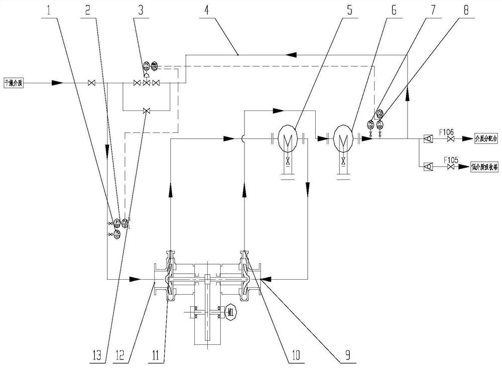
[0020] Such as figure 1 As shown, an anti-surge device for a centrifugal compressor includes a primary air intake pressure gauge 1, a primary pressure remote transmitter 2, an automatic regulating valve 3, a unit return pipeline 4, and a final exhaust pressure gauge 7. Final stage pressure remote transmitter 8. After the above-mentioned device is connected with the compressor unit, anti-surge of the centrifugal compressor can be realized. The compressor unit includes a compressor, an interstage cooler 5, a final stage cooler 6, and a host computer.

[0021] The primary air inlet pressure gauge 1 and the primary pressure remote transmitter 2 are arranged on the connecting pipe of the primary air inlet 12 of the compressor, and the primary air inlet 12 of the compressor is connected to the connecting pipe through a flange; The first-stage exhaust port 11 is connected ...


PUM


Abstract

The invention relates to an anti-surge device of a centrifugal compressor. The device comprises a first-stage air inlet pressure gauge, a first-stage pressure remote transmission transmitter, an automatic regulating valve, a unit backflow pipeline, a last-stage exhaust pressure gauge and a last-stage pressure remote transmission transmitter. After the above devices are connected with a compressor unit, surge prevention of the centrifugal compressor is achieved. By means of the compressor inlet and outlet compression ratio, backflow of the centrifugal compressor is automatically controlled to prevent surge of the compressor. Influences of air inlet and exhaust conditions are comprehensively considered, and the situation that due to the fact that the air inlet state of the compressor deviates from a design value, assumed conditions for controlling backflow of the compressor cannot stably exist, and equipment is extremely likely to surge before the predicted backflow condition is met is avoided. A plurality of on-site pressure data and remote transmission pressure data can be compared, so that the device is more effective, practical and reliable than other centrifugal compressor backflow anti-surge methods.

Description

technical field [0001] The invention belongs to the technical field of centrifugal compressors, and relates to an anti-surge device for centrifugal compressors. Background technique [0002] The basic working principle of the centrifugal compressor is to use the high-speed rotating impeller to do work on the gas, and use mechanical energy to increase the pressure and speed of the gas. After the gas leaves the impeller, it flows through the diffuser for reduced-speed expansion, so that the kinetic energy of the gas is converted into pressure energy, and the compression process is completed. [0003] When the flow rate of the centrifugal compressor is excessively reduced, the gas will stall relative to the impeller flow channel, and the gas flow rate and exhaust pressure of the compressor fluctuate periodically at low frequency and greatly, causing strong vibration of the machine. This phenomenon is called surge for the compressor. Surge is an inherent characteristic of cent...

Claims


Application Information

Patent Timeline
Patent Type & Authority Applications(China)
IPC IPC(8): F04D27/02F04D29/58
CPCF04D27/0276F04D29/5833
Inventor 杨金顺钱华林李啸
Owner 浙江宸轩透平机制造有限公司
Why Eureka
Try Eureka