Check patentability & draft patents in minutes with Patsnap Eureka AI!

Reinforcement type drive-by-wire brake

A brake-by-wire and booster technology, which is applied in the direction of brakes, brake types, axial brakes, etc., can solve the problems of slow braking response and increase the braking distance of the vehicle, so as to improve the braking response speed and reduce the installation The effect of space, high control precision

Active Publication Date: 2021-05-07
SHANDONG JIAOTONG UNIV
View PDF9 Cites 0 Cited by
  • Summary
  • Abstract
  • Description
  • Claims
  • Application Information

AI Technical Summary

Problems solved by technology

In order to ensure sufficient braking torque, the main technical solution currently adopted is the motor acceleration and deceleration mechanism, but the deceleration mechanism will cause slow braking response and increase the braking distance of the vehicle

Method used


Image

  • Reinforcement type drive-by-wire brake
  • Reinforcement type drive-by-wire brake
  • Reinforcement type drive-by-wire brake

Examples


Embodiment Construction

[0028] In order to clearly illustrate the technical features of this solution, the following describes this solution through a specific implementation mode and in conjunction with the accompanying drawings.

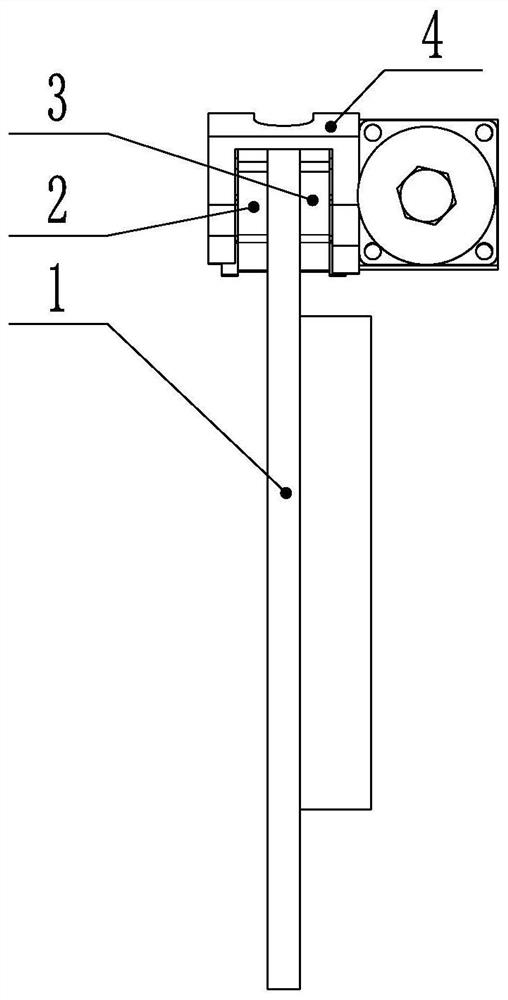
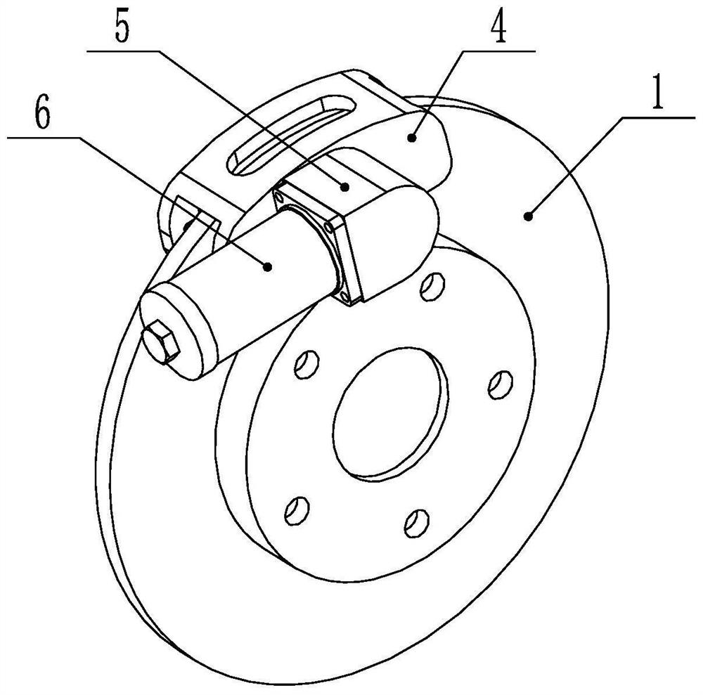
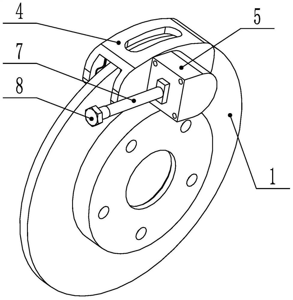
[0029] A boost-by-wire brake with a modular design such as figure 1 , figure 2 , image 3 , Figure 4 As shown, it includes brake disc 1, left friction plate 2, right friction plate 3, caliper 4, cylinder body 5, electromagnetic coil assembly 6, magnetostrictive rod 7, adjusting bolt 8, wedge 9, piston 10, rubber Circle 11; described electromagnetic coil assembly 6, magnetostrictive bar 7 form magnetostrictive actuator;

[0030] The brake disc 1 is connected with the axle bolts, and the left friction plate 2 and the right friction plate 3 are installed on the left and right sides of the brake disc 1 respectively, and the left friction plate 2 and the right friction plate 3 pass through the back of the brake disc 1 respectively. The steel sheet is installed in the mat...


PUM


Abstract

The invention relates to a reinforcement type drive-by-wire brake. The reinforcement type drive-by-wire brake adopts a modular design and comprises a brake disc, a left friction plate, a right friction plate, calipers, a cylinder body, an electromagnetic coil assembly, a magnetostrictive rod, an adjusting bolt, a wedge block, a piston and a rubber ring, wherein the electromagnetic coil assembly and the magnetostrictive rod form a magnetostrictive actuator, when a vehicle is braked, a vehicle controller controls the magnitude of current in an electromagnetic coil to change the intensity of a magnetic field, then the extension length of the magnetostriction rod is controlled, when the magnetostriction rod extends, the wedge block is pushed to move forwards, the wedge face on the wedge block presses and pushes the piston to move, the piston presses the right friction plate, and braking torque is generated under the combined action of the left friction plate and the right friction plate. According to the reinforcement type drive-by-wire brake, the magnetostrictive actuator is adopted as a power source of the brake, a wedge type force amplifier is combined, higher response frequency and control precision are achieved, the braking distance can be effectively shortened, and the vehicle running safety is improved.

Description

technical field [0001] The invention relates to the field of automobile brakes, in particular to a booster type wire-controlled brake. Background technique [0002] Brake-by-wire technology is a new type of braking technology that has emerged in recent years. It does not rely on mechanical or hydraulic connections between the brake and the brake pedal. It uses wires to replace part or all of the brake pipelines, and controls the electronic control through the controller. The components are used to control the braking force and realize the stable and reliable braking control of the car. At present, the brake-by-wire system mainly includes two types: electro-hydraulic brake system (EHB) and electro-mechanical brake system (EMB). The brake-by-wire system is conducive to the optimization of the braking performance of the whole vehicle, and can be easily integrated with other electronic control systems such as ABS, ASR, ESP, etc., so it has a broad development space. Especially...

Claims


Application Information

Patent Timeline
Patent Type & Authority Applications(China)
IPC IPC(8): F16D55/226F16D65/18B60T8/1761F16D121/28F16D125/66
CPCF16D55/226F16D65/18B60T8/1761F16D2121/28F16D2125/66
Inventor 张竹林王金波蒋德飞邹彦冉阮帅许本博
Owner SHANDONG JIAOTONG UNIV
Features
  • R&D
  • Intellectual Property
  • Life Sciences
  • Materials
  • Tech Scout
  • Unparalleled Data Quality
  • Higher Quality Content
  • 60% Fewer Hallucinations
Learn More