
Head/knee joint multipurpose radio frequency coil device based on 7.0t magnetic resonance imaging system

A magnetic resonance imaging and radio frequency coil technology, applied in magnetic resonance measurement, measurement devices, applications, etc., can solve problems such as diagnostic limitations, signal loss, and cumbersome operations, and achieve the effects of tapping application potential and improving imaging range

Active Publication Date: 2021-10-26
FUDAN UNIV
View PDF10 Cites 0 Cited by
  • Summary
  • Abstract
  • Description
  • Claims
  • Application Information

AI Technical Summary

Problems solved by technology

[0008] In order to solve a series of defects in the existing head and knee joint devices, such as small image range, serious signal loss, cumbersome operation, low inspection efficiency, and high equipment investment cost, the purpose of the present invention is to provide a widely applicable The head / knee joint multi-purpose radio frequency coil device with a global imaging field of view is easy and simple to use, and the equipment is highly integrated.
Under the premise that the imaging quality is fully guaranteed, it not only solves the problem of small brain imaging range and limited diagnosis, but also simplifies the scanning process, and does not need to replace the equipment when switching between head examination and knee joint examination, which greatly improves the The efficiency of inspection reduces the burden of clinical workers and avoids the potential risk of equipment damage during the replacement process; at the same time, only one device can be purchased to meet the diversity of inspections, which greatly reduces the cost of equipment

Method used


Image

  • Head/knee joint multipurpose radio frequency coil device based on 7.0t magnetic resonance imaging system
  • Head/knee joint multipurpose radio frequency coil device based on 7.0t magnetic resonance imaging system
  • Head/knee joint multipurpose radio frequency coil device based on 7.0t magnetic resonance imaging system

Examples


Embodiment Construction

[0036] The present invention will be further described below in combination with the accompanying drawings and specific embodiments.

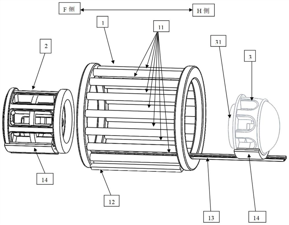
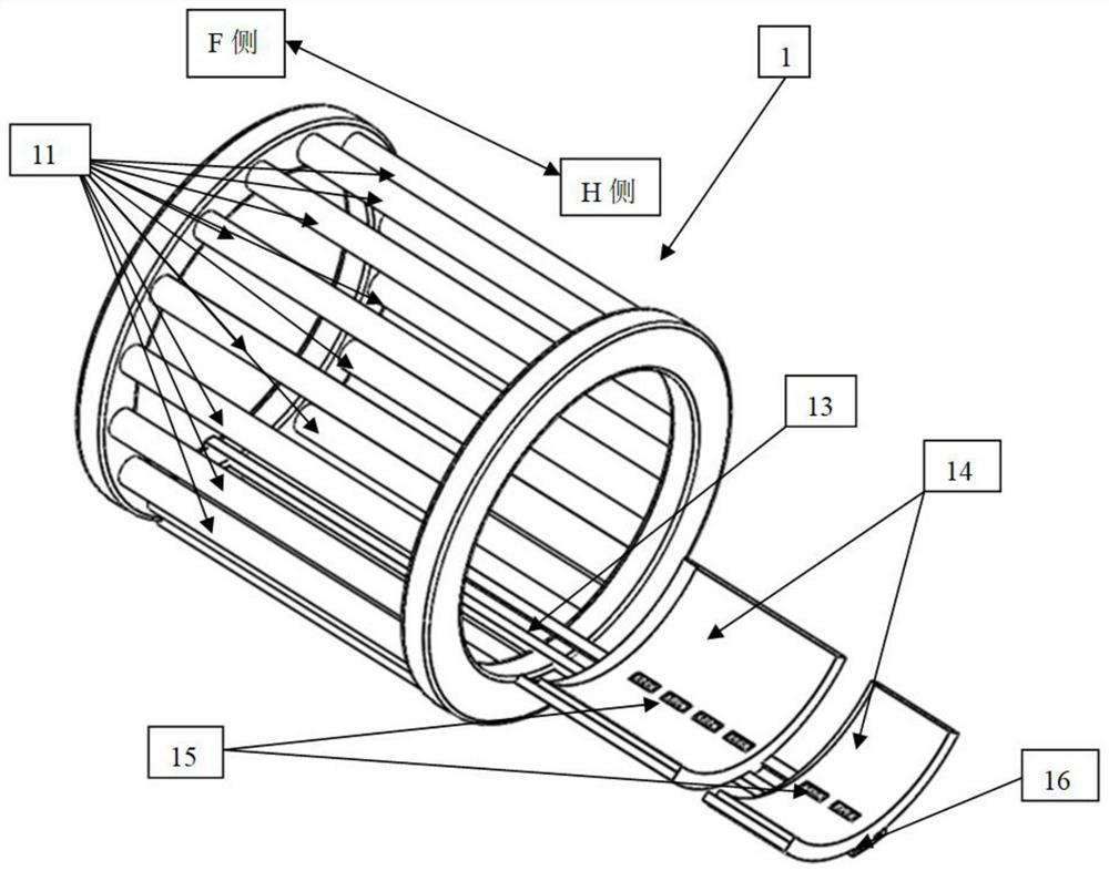
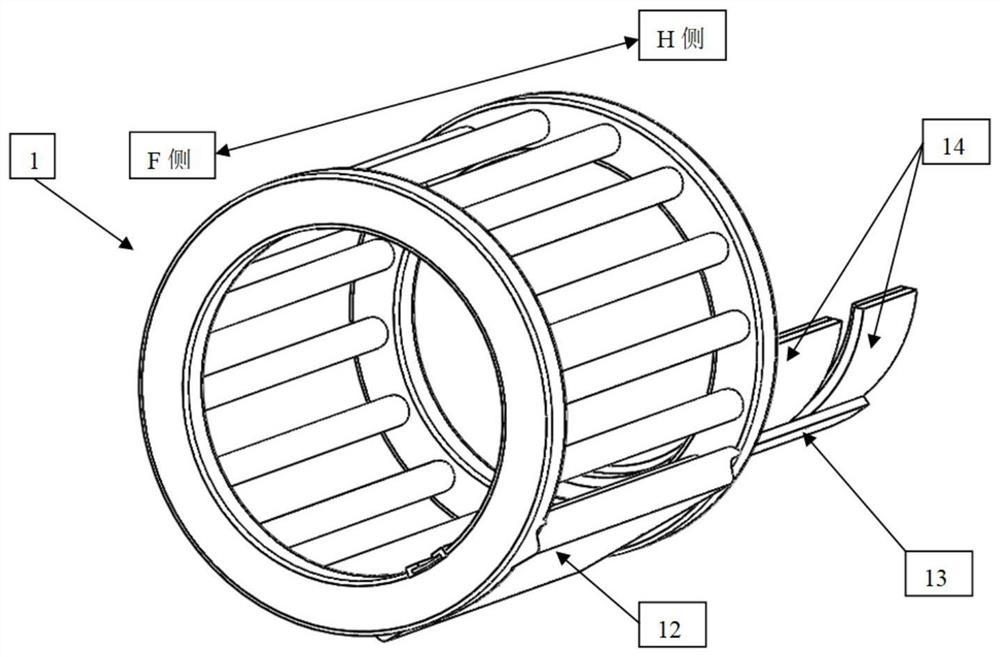
[0037] Such as figure 1 As shown, it is a schematic diagram of the overall structure of the head / knee joint multipurpose radio frequency device of the present invention, which is mainly composed of three parts: 1. a circularly polarized transmission system 1 for exciting magnetic resonance signals; 2. for receiving the knee joint and Knee joint receiving array group 2 for peripheral magnetic resonance signals; 3. Brain receiving array group 3 for receiving brain magnetic resonance signals. For the current 7.0T magnetic resonance system, the whole coil is no longer integrated as the signal transmission system, mainly because in the ultra-high field environment, if the whole coil is used as the transmission, because it excites the entire volume environment The proton signal in the test requires a strong power to excite, which not only puts a hig...


PUM


Abstract

The invention belongs to the technical field of magnetic resonance imaging, in particular to a head / knee joint multipurpose radio frequency coil device based on a 7.0T magnetic resonance imaging system. The device of the present invention includes a circularly polarized transmitting system for exciting magnetic resonance signals, an array receiving system for receiving magnetic resonance signals (including a receiving array combination for collecting knee joint magnetic resonance signals and a receiving array combination for collecting cranial magnetic resonance signals) ), used to fix and connect the transceiver system, and the chute guide rail that can switch equipment according to different scanning purposes. The transmitting system and receiving system use plastic without proton signals as the radio frequency circuit carrier and shell, and radio frequency channels are set inside. In the 7.0T ultra-high-field clinical magnetic resonance system, the present invention can use a single device to perform imaging functions on multiple parts while ensuring that the imaging quality remains unchanged, which will greatly reduce the cost, and does not require frequent replacement during the inspection process equipment, greatly increasing the efficiency of clinical examinations.

Description

technical field [0001] The invention belongs to the technical field of magnetic resonance imaging, and in particular relates to a radio frequency coil device used in a human organ magnetic resonance imaging system, in particular to a head / knee joint multipurpose radio frequency coil device. Background technique [0002] Magnetic resonance imaging (MRI) is an application of nuclear magnetic resonance (NMR) in medicine. The main magnetic system of the magnetic resonance imaging system produces a uniform strong magnetic field (called the main magnetic field of the MRI system—B 0 ). The hydrogen nuclei in the human body are in B 0 Spin polarization occurs under the field. The magnetically polarized hydrogen nucleus spins generate a magnetic moment i in the human body. in the absence of B 0 In the case of excitation by an external magnetic field other than , the magnetic moment is in a steady state, and the direction and the main magnetic field B 0 Orientation is coaxial an...

Claims


Application Information

Patent Timeline
Patent Type & Authority Patents(China)
IPC IPC(8): G01R33/36A61B5/00A61B5/055
CPCA61B5/055A61B5/4064A61B5/4585G01R33/3664
Inventor 王鹤方磊
Owner FUDAN UNIV
Learn More