
Device and method for realizing welding of array optical fiber and large-size quartz end cap

A technology of arrayed optical fibers and quartz end caps, which is applied in the field of fusion splicing devices between arrayed optical fibers and large-sized quartz end caps, can solve the problems of compactness and light weight of the beam combining device, poor beam quality, and shrinkage of the beam, and achieve an improvement The effect of welding quality, releasing welding stress, and high integration

Active Publication Date: 2021-05-07
SHANGHAI INST OF OPTICS & FINE MECHANICS CHINESE ACAD OF SCI
View PDF6 Cites 1 Cited by
  • Summary
  • Abstract
  • Description
  • Claims
  • Application Information

AI Technical Summary

Problems solved by technology

However, in the actual synthesis system, the beam quality of the synthesized light is worse than that of a single fiber input laser, which is mainly affected by factors such as the disturbance of the laser array, the aberration of the conversion lens, the thermal distortion of the diffraction grating, and the line width of the array light source. Impact
[0003] Since the single fiber output head needs to be mechanically clamped and water-cooled in the spectral beam combining device, the distance Δx between adjacent fibers cannot be reduced without limit, and the beam combining device cannot be made compact and lightweight, which limits high-brightness fiber lasers Applications on motorized platforms

Method used


Image

  • Device and method for realizing welding of array optical fiber and large-size quartz end cap
  • Device and method for realizing welding of array optical fiber and large-size quartz end cap
  • Device and method for realizing welding of array optical fiber and large-size quartz end cap

Examples


Embodiment Construction

[0041] In order to make the above-mentioned features and effects of the present invention more comprehensible, specific implementations of the present invention will be described in detail below in conjunction with the accompanying drawings. In the following description, numerous specific details are set forth in order to provide a thorough understanding of the present invention. However, the present invention can be implemented in a variety of ways other than those described here, and those skilled in the art can make similar improvements without departing from the connotation of the present invention, so the present invention is not limited by the specific implementations disclosed below.

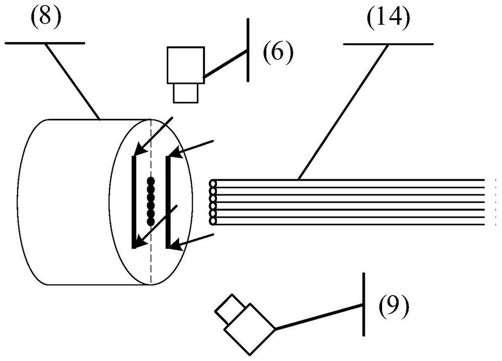
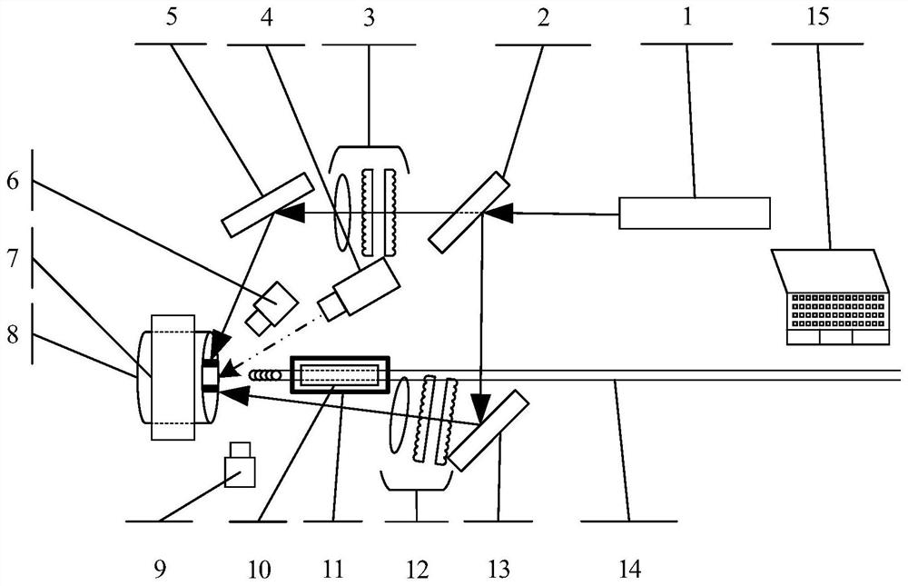
[0042] The device for realizing fusion splicing of an arrayed optical fiber and a large-sized quartz end cap according to an embodiment of the present invention will firstly be described in detail with reference to the accompanying drawings.

[0043] see figure 1 , figure 2 and image...


PUM


Abstract

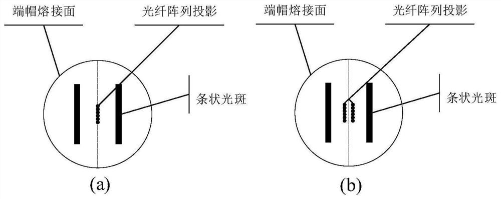
The invention discloses a device for realizing welding of an array optical fiber and a large-size quartz end cap. The device comprises a carbon dioxide laser, a spectroscope, a beam shaper, a high-reflectivity mirror, an image detection module, the array optical fiber and a carrier thereof, the large-size quartz end cap and a carrier thereof, a stepping motor, a thermodetector and a computer, a laser beam emitted by a carbon dioxide laser is divided into two beams of light through a spectroscope, the two beams of light are shaped into two beams of strip-shaped light spots with uniform power density to heat a welding surface of the large-size quartz end cap after respectively passing through a beam shaper and a high-reflectivity mirror, and a uniform temperature field of a target welding area is realized through indirect heating and heat conduction; and when the temperature of the welding area reaches the preset temperature, the stepping motor is driven to make the array optical fiber translate to the welding area at a constant speed to be fused and overlapped with the end cap, and one-time welding of the array optical fiber can be achieved. The array optical fiber end cap formed by welding the array optical fiber and the large-size quartz end cap is favorable for optimizing the light beam quality of synthesized light of a spectrum synthesis system and realizing compactness and light weight of a beam combining device.

Description

technical field [0001] The invention belongs to the field of fusion splicing of optical fiber end caps, and in particular relates to a fusion splicing device and method for an array optical fiber and a large-size quartz end cap. Background technique [0002] High-brightness fiber lasers have broad application prospects in industrial, medical, national defense and other fields. Limited by nonlinear effects, mode instability effects, and material damage characteristics, there is a theoretical limit to the output power of a single-channel single-mode fiber laser. Multi-beam combining technology is an important technical way to achieve high-power and high-beam-quality laser output. Through a specific beam combining method, not only can the output laser power be increased, but also the output laser can be guaranteed to have excellent beam quality. Among them, the spectral synthesis technology has the advantages of good output beam quality, no requirement for the sub-beam phase, ...

Claims


Application Information

Patent Timeline
Patent Type & Authority Applications(China)
IPC IPC(8): G02B6/255
CPCG02B6/2551G02B6/2555G02B6/2808G02B6/3672G02B6/2553
Inventor 张海波吴梦浩何兵雷雨周军漆云凤袁志军叶韧
Owner SHANGHAI INST OF OPTICS & FINE MECHANICS CHINESE ACAD OF SCI
Learn More