Square motor

A square and rotor technology, applied in the direction of electromechanical devices, electrical components, electric components, etc., can solve the problems of low housing space utilization, non-adjustable air gap magnetic field, permanent magnet falling off, etc., to improve stability and service life, and improve The effect of air gap space utilization and increasing the amplitude of back EMF

Pending Publication Date: 2021-05-07
NINGBO JINGCHENG CAR IND
View PDF6 Cites 0 Cited by
  • Summary
  • Abstract
  • Description
  • Claims
  • Application Information

AI Technical Summary

Problems solved by technology

However, the motor with such a shape structure has the following problems: it is easy to roll during transportation; it is inconvenient to install and requires an additional positioning motor
Although this kind of motor with a square shell solves the shortcomings of the above-mentioned traditional cylindrical motor, it has the following problems: the space utilization rate of the shell is low, and the space at the four corners is not utilized; the air gap magnetic field is not adjustable; the efficiency of the motor is low. Low
In addition, the permanent magnet is adhered to the shell, and the connection stability is low. At the same time, it is easy to be dislocated during installation, which makes disassembly and assembly more inconvenient. Large vibrations will easily cause the permanent magnet to fall off. The maintenance cost is high and the service life is low. Therefore, it is necessary to develop A New Type of Square Motor

Method used


Image

  • Square motor
  • Square motor
  • Square motor

Examples


Embodiment Construction

[0027]The present invention will be further described below with reference to the accompanying drawings and specific examples.

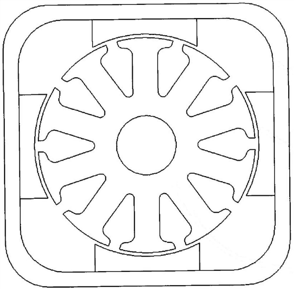
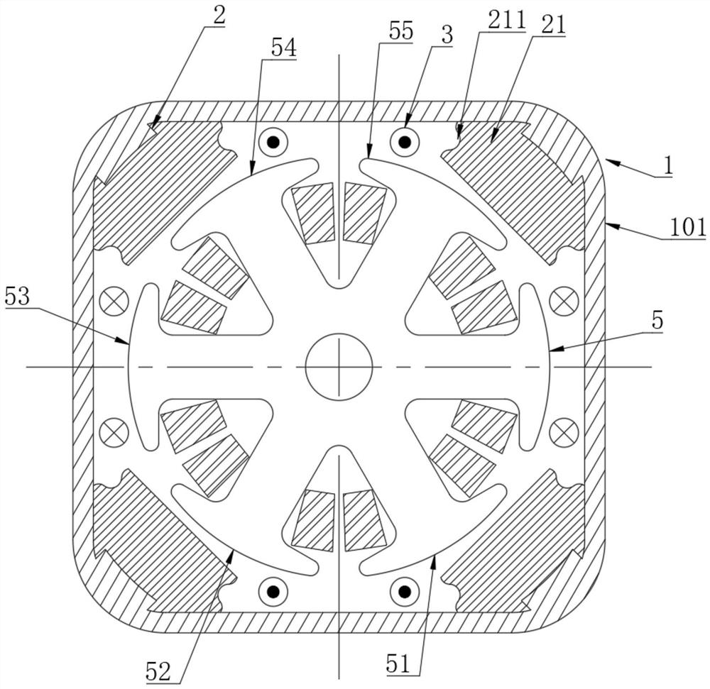
[0028]Seeimage 3 As shown, a square motor of the present invention comprises a stator and a rotor located within the stator comprising a housing 1 comprising several sidewalls 101, in adjacent two sidewalls 101 A boss 2 is provided between the boss 2, and the permanent magnet 21 is connected to the boss 2;

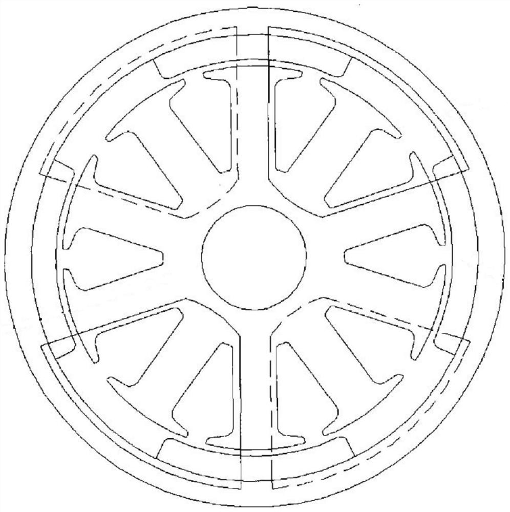
[0029]The permanent magnet 21 is facing a plane toward the center of the rotor, and the outer side of the rotor is an arc surface such that when the rotor is opposed to the permanent magnet 21, the outer surface of the rotor is formed between the permanent magnets 21 The air gap is evenly increased from the middle of the permanent magnet 21 to both sides;

[0030]The wire groove 211 is opened on both sides of the permanent magnet 21, and the excitation winding group 3 is rotated in the wire groove 211;

[0031]When assembled, the permanent magnet 21 with the boss ...


PUM


Abstract

The invention discloses a square motor. The square motor has the advantages of improved air gap flux density waveform, reduced torque pulsation, high motor efficiency and space utilization rate, convenience in production and machining. The square motor is characterized in that the square motor comprises a stator and a rotor located in the stator; the stator comprises a shell; the shell comprises a plurality of side walls; a boss is arranged between every two adjacent side walls; the shell is connected with permanent magnets through the bosses; and wire grooves are formed in the two sides of each permanent magnet, and excitation windings are wound around the wire grooves; The invention belongs to the technical field of motors.

Description

Technical field[0001]The present invention relates to the field of motor technology, and more particularly to a square motor.Background technique[0002]figure 1 As shown in a cross-sectional view of a conventional permanent magnet DC motor, such a motor is mounted in a cylindrical housing with a cylindrical housing, and the permanent magnet is fixed to the inside of the cylindrical housing and distributed around the rotor. However, the motor having such a profile structure has the following problems: it is easy to scroll during the transportation; the installation is inconvenient, and additional positioning motors are required.figure 2 A square motor developed by the industry in recent years, such a motor adopts square housing, and the permanent magnet is mounted on the four sides of the outer surface of the outer casing, and the rotor is mounted in the housing, and the permanent magnet is distributed around the rotor. Although the motor of the square housing solves the deficiencies ...

Claims


Application Information

Patent Timeline
Patent Type & Authority Applications(China)
IPC IPC(8): H02K1/17H02K1/18H02K1/16H02K3/28H02K1/24H02K5/04H02K21/28H02K21/04
CPCH02K1/17H02K1/185H02K1/165H02K3/28H02K1/24H02K5/04H02K21/28H02K21/04H02K2201/03
Inventor 任成波周开放李文亮徐盼
Owner NINGBO JINGCHENG CAR IND
Why Eureka
Try Eureka