
Crusher for construction machinery

A technology for construction machinery and crushers, applied in grain processing, separation of dispersed particles, chemical instruments and methods, etc., can solve problems such as air pollution, incomplete crushing of materials, failure of crushers to perform circular crushing, etc.

Pending Publication Date: 2021-05-11
李良容
View PDF6 Cites 0 Cited by
  • Summary
  • Abstract
  • Description
  • Claims
  • Application Information

AI Technical Summary

Problems solved by technology

[0004] Aiming at the deficiencies of the prior art, the present invention provides a crusher for construction machinery, which solves the problem that the crusher cannot perform cyclic crushing during the processing process, resulting in incomplete crushing of many materials, and there are still many large volumes, and the crusher During the working process, a lot of internal smoke and dust are directly discharged through the cooling vent, causing air pollution problems

Method used


Image

  • Crusher for construction machinery
  • Crusher for construction machinery
  • Crusher for construction machinery

Examples


Embodiment 1

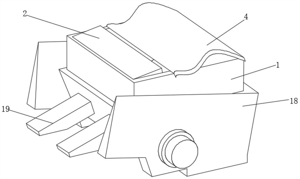
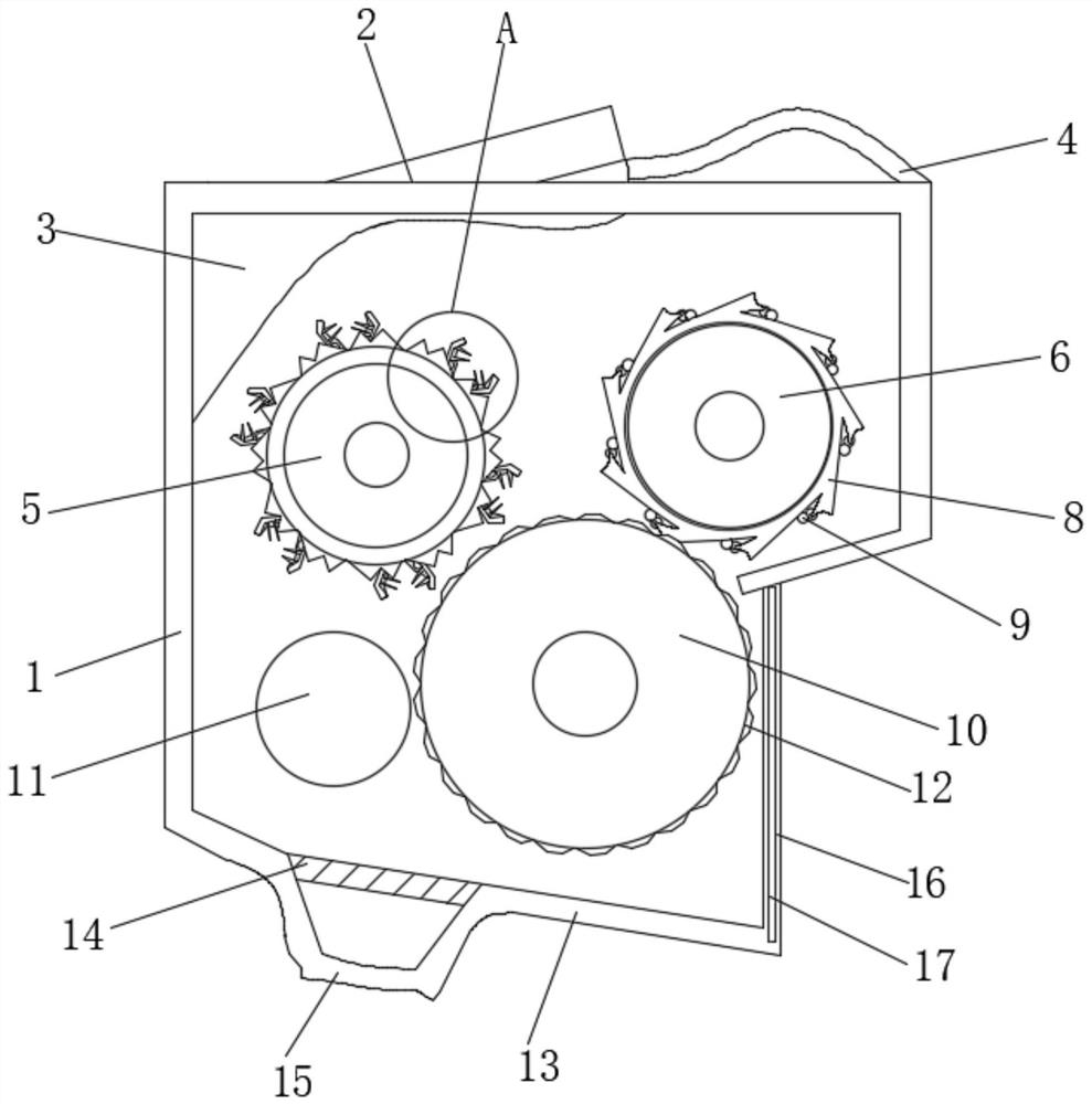
[0029] see Figure 1-2 , the present invention provides a technical solution: a crusher for construction machinery, comprising a box body 1, the top of the box body 1 is provided with a material inlet, the inner surface of the material inlet is rotatably connected to a box cover 2, and the box cover 2 The bottom is fixedly connected with a buffer pad 3, the right side of the top of the box body 1 is slidingly connected with a semi-permeable plate 4, the inner surface of the box body 1 is respectively connected with a crushing shaft 5 and a reverse shaft 6, and the outer surface of the crushing shaft 5 is evenly connected There is a fixing mechanism 7, the outer surface of the reverse shaft 6 is evenly and fixedly connected with a reverse baffle 8, the outer surface of the reverse baffle 8 is evenly and fixedly connected with balls 9, the inner surface of the box body 1 is located near the crushing shaft 5 One side is connected with an auxiliary roller 10 for rotation, and the ...

Embodiment 2

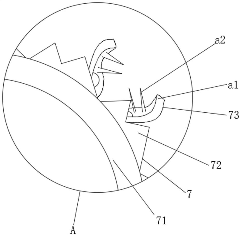
[0031] see Figure 2-4 , the present invention provides a technical solution: the fixing mechanism 7 includes a circular casing 71, the inner surface of the circular casing 71 is fixedly connected with the outer surface of the crushing shaft 5, and the outer surface of the circular casing 71 is evenly and fixedly connected with a cone The outer surface of the shaped tooth 72 and the tapered tooth 72 are uniformly and fixedly connected with a clamping assembly 73 . After the material is fixed, it can be crushed. Through the cooperation of the conical teeth 72 and the auxiliary roller 10, the distance between the two is shortened, the friction to the material is increased, and the crushing force is increased. After the internal puncture assembly a2 clamps the material, it is not easy to fall off, and it is fixed and directly sent between the crushing shaft 5 and the auxiliary roller 10 .

[0032] The clamping assembly 73 includes an arc-shaped blade a1, the bottom of which is r...


PUM


Abstract

The invention discloses a crusher for construction machinery, and relates to the technical field of construction. The crusher for the building machinery comprises a box body, a feeding port is formed in the top of the box body, a box cover is rotatably connected to the inner surface of the feeding port, a buffer pad is fixedly connected to the bottom of the box cover, a semi-permeable plate is slidably connected to the right side of the top of the box body, a crushing shaft and a reverse shaft are rotatably connected to the inner surface of the box body respectively, and the outer surface of the crushing shaft is uniformly connected with fixing mechanisms. The crushing shaft, an auxiliary roller, the reverse shaft and a fixed rubber shaft are arranged in the crushing box, and the four shafts are used together. If materials cannot be crushed, the materials cannot fall down through the fixed rubber shaft according to the size, and the materials can move back and forth in the box body along with the auxiliary roller, and fall down and are collected until the materials are completely crushed by the crushing shaft. Under the action of the reverse shaft, the materials can only fall from the left side, and the crushing efficiency of the machine is improved.

Description

technical field [0001] The invention relates to the technical field of construction, in particular to a crusher for construction machinery. Background technique [0002] The roller crusher is suitable for crushing medium and high hardness materials in metallurgy, building materials, refractories and other industrial sectors. This series of double-roll crushers is mainly composed of rollers, roller support bearings, pressing and adjusting devices, and driving devices. Adjustment of discharge granularity: a wedge or gasket adjustment device is installed between the two rollers, and an adjustment bolt is installed on the top of the wedge device. When the adjustment bolt pulls up the wedge, the wedge pushes the movable roller away from the fixed wheel. . [0003] The existing crushers used for building materials cannot crush the materials with appropriate strength according to the size of the materials after they are fed into the crusher, and the crushers cannot perform cyclic...

Claims


Application Information

Patent Timeline
IPC IPC(8): B02C4/08B02C4/30B02C4/28B02C4/44B01D46/10
CPCB01D46/10B02C4/08B02C4/28B02C4/30B02C4/44
Inventor 李良容
Owner 李良容
Learn More