
Electrically-driven axle device and electrically-driven transport vehicle

A technology for electric drive and transport vehicles, which is applied in the fields of electric drive transport vehicles and electric drive axle devices. It can solve the problems of inconvenient installation and maintenance of drive motors, deformation of output shafts, and reduced service life of drive motors. It achieves simple structure and easy operation. Stable, stable and reliable installation

Active Publication Date: 2021-05-11
MCC BAOSTEEL TECH SERVICE
View PDF9 Cites 3 Cited by
  • Summary
  • Abstract
  • Description
  • Claims
  • Application Information

AI Technical Summary

Problems solved by technology

[0003] However, most of the electric drive axles that appear in the new market are electric transformations on traditional axles. In the electric axle structure, the output shaft of the drive motor is connected to the wheel shaft, so that the force of the wheel is directly transmitted to the wheel. group, and deform the output shaft of the drive motor connected to it, which indirectly reduces the service life of the drive motor, and the drive motor is installed in the axle body, which is not convenient for the installation and maintenance of the drive motor

Method used


Image

  • Electrically-driven axle device and electrically-driven transport vehicle
  • Electrically-driven axle device and electrically-driven transport vehicle
  • Electrically-driven axle device and electrically-driven transport vehicle

Examples


Embodiment Construction

[0065] The implementation of the present invention will be illustrated by specific specific examples below, and those skilled in the art can easily understand other advantages and effects of the present invention from the contents disclosed in this specification.

[0066] It should be noted that the structures, proportions, sizes, etc. drawn in the drawings of this specification are only used to match the content disclosed in the specification, for those who are familiar with this technology to understand and read, and are not used to limit the conditions for the implementation of the present invention. Therefore, there is no technical substantive meaning, and any modification of structure, change of proportional relationship or adjustment of size shall still fall within the scope of the disclosure of the present invention without affecting the functions and objectives of the present invention. within the scope of technical content. At the same time, terms such as "upper", "lo...


PUM


Abstract

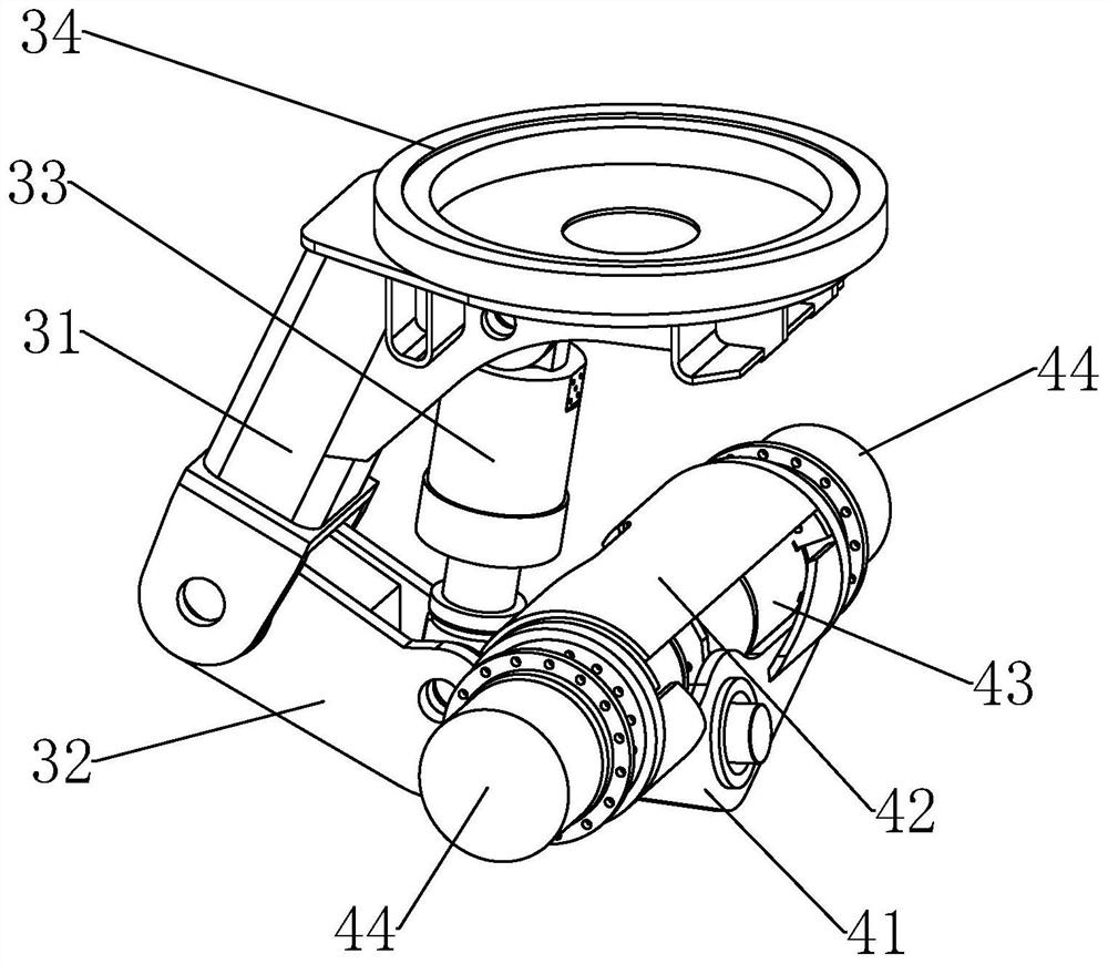
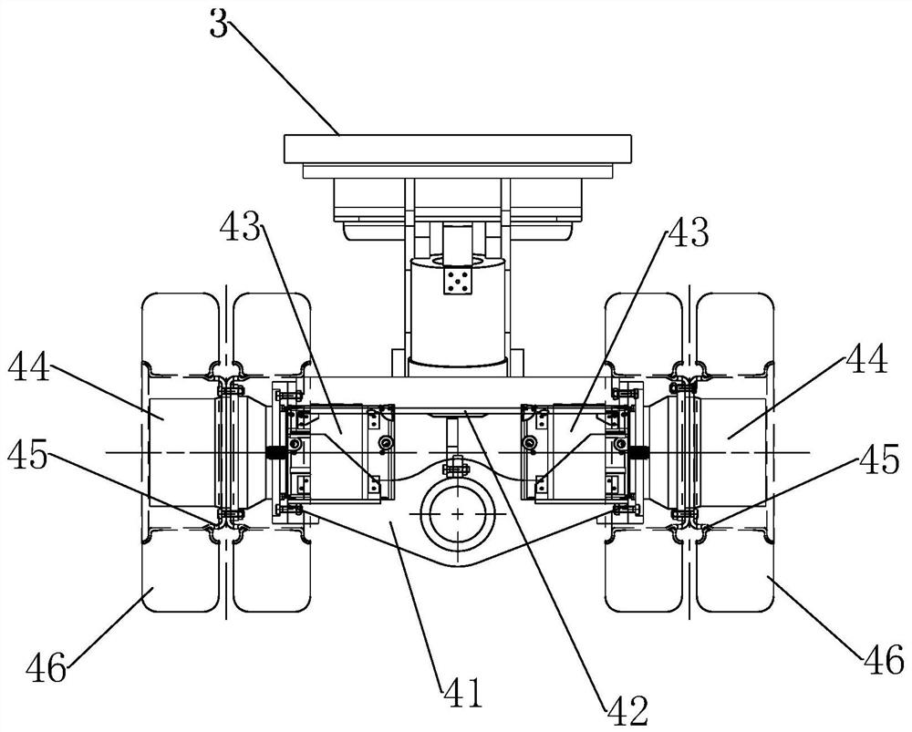
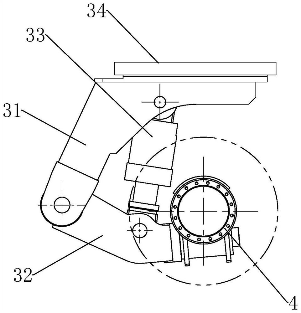
The invention relates to an electrically-driven axle device and an electrically-driven transport vehicle, wherein the electrically-driven axle device comprises an axle support, driving motors, hub reduction gears and rims; the axle support comprises a connecting main base and connecting flanges symmetrically fixed on the left side and the right side of the connecting main base; motor mounting spaces are defined by the inner side faces of the connecting flanges and the upper end of the connecting main base; mounting bolt holes are formed in the connecting flanges, the driving motors are located in the motor mounting spaces and fixedly connected to the inner side faces of the connecting flanges through bolts, and the hub reduction gears are connected to the outer side faces of the connecting flanges through bolts; an output shaft of each driving motor is connected with the corresponding wheel-side speed reducer, the wheel-side speed reducers are each provided with a rotating output flange, and each rim is connected with the rotating output flange of the corresponding wheel-side speed reducer through a bolt. The electrically-driven axle device is simple in structure and stable in operation, deformation of the output shafts of the driving motors can be effectively prevented, and the driving motors are convenient to install and maintain.

Description

technical field [0001] The invention relates to the field of vehicle drive, in particular to an electric drive axle device and an electric drive transport vehicle. Background technique [0002] At present, most of the iron-water electric drive transport vehicles used in the smelting production line adopt a hydraulic drive system, which includes hydraulic steering, hydraulic drive axles, hydraulic lifts, etc. Factors such as climbing, bumping and vibration, or overweight transportation can easily cause the internal pressure of the hydraulic system to reach the maximum value in an instant, which will cause the seal to deform instantly, but it will take a certain time for the seal to return to its normal shape after the instant pressure is released, which is likely to cause hydraulic oil. Leakage; the second is the temperature emitted by molten iron during transportation, and the long-term work of the hydraulic system makes the oil temperature of its own hydraulic system rise. ...

Claims


Application Information

Patent Timeline
IPC IPC(8): B60B35/00B60B35/12B62D5/12
CPCB60B35/004B60B35/006B60B35/122B62D5/12
Inventor 邱冬平耿会良李利民张吉胜杨琳
Owner MCC BAOSTEEL TECH SERVICE
Learn More