
Safe high-speed stacking machine

A stacker and safe technology, applied in the field of technical stackers, can solve the problems of uncompact structure, large wear, high power of equipment, etc.

Active Publication Date: 2021-05-11
浙江中扬立库技术有限公司
View PDF6 Cites 0 Cited by
  • Summary
  • Abstract
  • Description
  • Claims
  • Application Information

AI Technical Summary

Problems solved by technology

[0004] The purpose of the present invention is to provide a safe high-speed stacker to solve the above-mentioned background technology. The existing light stacker on the market is improved on the basis of the original column straight rail stacker. The heavy-duty square tube column form is heavy; the lifting generally adopts the original hoist form, which is heavy and low in speed; the light stacker close to the present invention is still in the improved form of double columns, and the ground rail is generally steel light rail, and the walking wheels The wheel body is made of steel; the loading platform is made of welded channel steel and rectangular tubes, which is heavy and heavy, and the speed is low, and the equipment weighs more than 2 tons. The equipment has high power and energy consumption. Compact, low speed, low safety factor, the track and wheel body are made of carbon steel, with high noise and high wear, the device body is too heavy, resulting in low speed and low efficiency, while the ordinary light stacker has no stall protection device question

Method used


Image

  • Safe high-speed stacking machine
  • Safe high-speed stacking machine
  • Safe high-speed stacking machine

Examples


Embodiment Construction

[0030]The following will clearly and completely describe the technical solutions in the embodiments of the present invention with reference to the accompanying drawings in the embodiments of the present invention. Obviously, the described embodiments are only some, not all, embodiments of the present invention. Based on the embodiments of the present invention, all other embodiments obtained by persons of ordinary skill in the art without making creative efforts belong to the protection scope of the present invention.

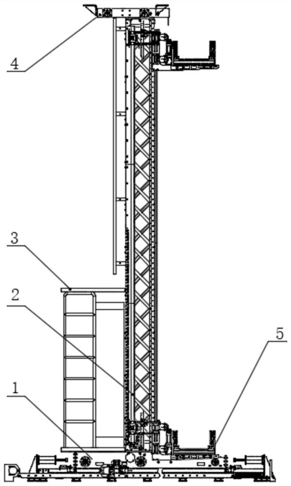
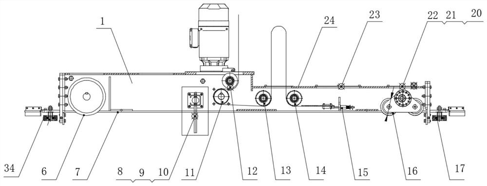
[0031] see Figure 1-9 , the present invention provides a technical solution: a safe high-speed stacker, including a lower beam assembly 1, a column assembly 2 is arranged on the top of the lower beam assembly 1, and an electric control platform 3 is fixedly connected to one side of the column assembly 2, The other side of the column assembly 2 is movably installed with a cargo platform assembly 5, the top of the column assembly 2 is provided with an upper beam...


PUM


Abstract

The invention discloses a safe high-speed stacking machine. The machine comprises a lower cross beam assembly, a stand column assembly is arranged at the top of the lower cross beam assembly, an electric control platform is fixedly connected to one side of the stand column assembly, a cargo carrying table assembly is movably installed at the other side of the stand column assembly, and an upper beam assembly is arranged at the top of the stand column assembly; a walking movable wheel assembly is arranged in one side of the lower cross beam assembly; through a second synchronous belt inner side tensioning assembly and a synchronous belt lower end tensioning assembly which are designed, and through the layout design of adopting a chain or a synchronous belt for lifting and the like, the structure is compact, the speed is high, the safety is high, and lifting driving is achieved, the lifting stress structure is more reasonable, and the service life of a transmission part is greatly prolonged; and meanwhile, tensioning of the chain or the synchronous belt and the like is more reasonable, teeth are not prone to disengagement, large equipment power and large energy consumption are avoided, and meanwhile the problems that a winch manner adopted for lifting is not compact in structure, low in speed and low in safety coefficient are solved.

Description

technical field [0001] The invention belongs to the field of technical stackers, in particular to a safe high-speed stacker. Background technique [0002] The early stacker is to hang a gantry column on the lifting trolley of the bridge crane, and use the up and down movement of the fork on the column and the rotation of the column to carry the goods, usually called bridge stacker, in 1960 Roadway stackers appeared in the United States around the world. This kind of stacker used ground rails to prevent dumping. Later, with the development of computer control technology and automated three-dimensional warehouses, the use of stackers became more and more extensive. It is getting better and better, and the height is getting higher and higher. Today, the height of the stacker can reach 40 meters. In fact, if it is not limited by warehouse construction and cost, the height of the stacker can be higher. The stacker is the core equipment of the automated intelligent warehouse. It ...

Claims


Application Information

Patent Timeline
IPC IPC(8): B66F9/07B66F9/075B66F9/08
CPCB66F9/07B66F9/072B66F9/075B66F9/08Y02W30/40
Inventor 陈新安王开胜林奇峰吴楠刘季晶马佳利蔡添
Owner 浙江中扬立库技术有限公司
Learn More