
Pipe cavity exhaust device for main oil pipes and continuous wall grab machine

A technology of exhaust device and main oil pipe, applied in the field of cavity exhaust device and diaphragm wall grab machine, can solve the problems of waste of hydraulic oil spray, short life of hydraulic oil pipe, polluted environment, etc., so as to improve the service life and reduce bursting. , the effect of reducing the probability of pollution

Pending Publication Date: 2021-05-11
BEIJING SANY INTELLIGENT MFG TECH CO LTD
View PDF0 Cites 0 Cited by
  • Summary
  • Abstract
  • Description
  • Claims
  • Application Information

AI Technical Summary

Problems solved by technology

[0004] In view of this, the application provides a lumen exhaust device for the main oil pipe and a diaphragm wall grab machine, which solves the problem of waste and environmental pollution caused by hydraulic oil spraying during the commissioning process of the diaphragm wall grab machine in the prior art , the technical problem of short hydraulic oil pipe life

Method used


Image

  • Pipe cavity exhaust device for main oil pipes and continuous wall grab machine
  • Pipe cavity exhaust device for main oil pipes and continuous wall grab machine
  • Pipe cavity exhaust device for main oil pipes and continuous wall grab machine

Examples


Embodiment Construction

[0023] In the description of the present application, "plurality" means at least two, such as two, three, etc., unless otherwise specifically defined. All directional indications (such as up, down, left, right, front, back, top, bottom...) in the embodiments of the present application are only used to explain the relationship between the components in a certain posture (as shown in the accompanying drawings) If the specific posture changes, the directional indication will also change accordingly. Furthermore, the terms "include" and "have", as well as any variations thereof, are intended to cover a non-exclusive inclusion. For example, a process, method, system, product or device comprising a series of steps or units is not limited to the listed steps or units, but optionally also includes unlisted steps or units, or optionally further includes For other steps or units inherent in these processes, methods, products or apparatuses.

[0024] Additionally, reference herein to "...


PUM


Abstract

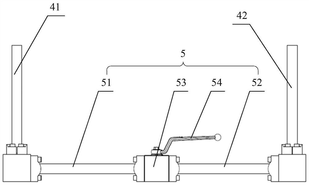
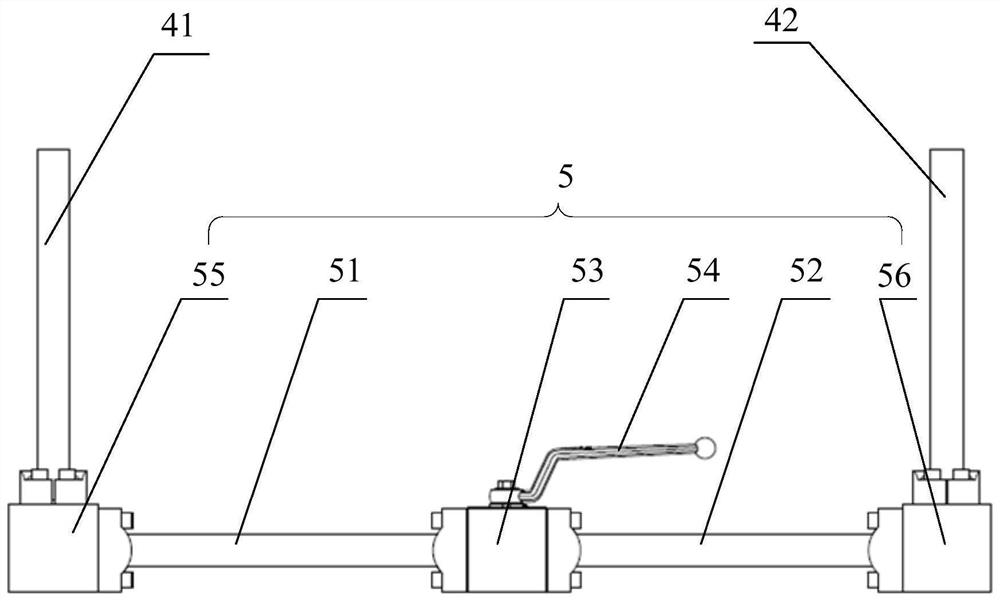
The invention provides a pipe cavity exhaust device for main oil pipes and a continuous wall grab machine. Through the device, the technical problems that in the debugging process of a continuous wall grab machine in the prior art, the environment is polluted, and the service life of a hydraulic oil pipe is short are solved. The pipe cavity exhaust device is used for balancing pressure between a first main oil pipe and a second main oil pipe. The pipe cavity exhaust device comprises a first connecting pipe, the first main oil pipe and a second connecting pipe which communicate with one another, wherein the second connecting pipe communicates with the second main oil pipe, and the first connecting pipe communicates with the first main oil pipe; and a first communicating piece is provided with a first switch, the first main oil pipe and the second main oil pipe communicate or not through opening or closing of the first switch, and the pressure in the first main oil pipe and the pressure in the second main oil pipe are balanced. Air in the first main oil pipe and air in the second main oil pipe are exhausted, therefore, the probability that the main oil pipes burst due to overhigh pressure in an oil injection pipe is lowered, the service life of the main oil pipes is prolonged, the probability that hydraulic oil is sprayed is lowered, and the probability that the environment is polluted is lowered.

Description

technical field [0001] The present application relates to the field of engineering machinery, in particular to a lumen exhaust device for main oil pipes and a diaphragm wall grab machine. Background technique [0002] The hose reel is one of the key components of the diaphragm wall grab machine, and its function is to wind and store the hydraulic oil pipe. When the working device in the diaphragm wall grab machine is digging downward, the hydraulic oil pipe on the drag reel is stretched out, so as to achieve the purpose of continuous work within a certain depth. And when the working device rises, the hose reel can provide a force opposite to the dragging force, so that the hydraulic oil pipe can be retracted automatically. [0003] Before the working device in the diaphragm wall grab machine works, the diaphragm wall grab machine needs to be debugged and assembled, that is, the hydraulic oil pipe needs to be filled with hydraulic oil, but in the process of filling the hydra...

Claims


Application Information

Patent Timeline
Patent Type & Authority Applications(China)
IPC IPC(8): E02F5/02E02F5/14
CPCE02F5/025E02F5/145
Inventor 张领陈兆鲁
Owner BEIJING SANY INTELLIGENT MFG TECH CO LTD
Learn More