Formwork system for building cast-in-place shear wall and filler wall and construction method

A shear wall and infill wall technology, which is applied in the on-site preparation of building components, formwork/formwork/work frame, formwork/formwork/work frame connectors, etc., can solve the problems affecting the total construction period and the turnover of formwork systems Problems such as low frequency and non-recyclability

Pending Publication Date: 2021-05-11
李洪宾
View PDF0 Cites 1 Cited by
  • Summary
  • Abstract
  • Description
  • Claims
  • Application Information

AI Technical Summary

Problems solved by technology

[0002] At present, China is affected by the development trend of land resources and buildings, and the number of high-rise and super high-rise shear wall structure buildings and prefabricated buildings of laminated panels is increasing; the formwork system in the traditional construction method has less turnover times, is easy to deform, and is affected by wood. Resource shortage, non-recyclable and other constraints, the cost continues to increase, and the removal of the shear wall formwork can only be carried out after the cast-in-place slab concrete is poured, and the demolition is affected by obstacles such as the supporting steel pipes at the bottom of the cast-in-place slab formwork, so the demolition and handling efficiency is very low , The labor cost is very high; Affected by the shortage of masonry human resources, the labor cost of the post-filling wall is also increasing, and the post-filling wall can only be constructed after the main concrete structure is completed and reaches a certain strength , affecting the total duration

Method used


Image

  • Formwork system for building cast-in-place shear wall and filler wall and construction method
  • Formwork system for building cast-in-place shear wall and filler wall and construction method
  • Formwork system for building cast-in-place shear wall and filler wall and construction method

Examples


Embodiment Construction

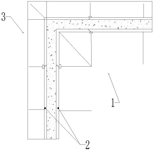
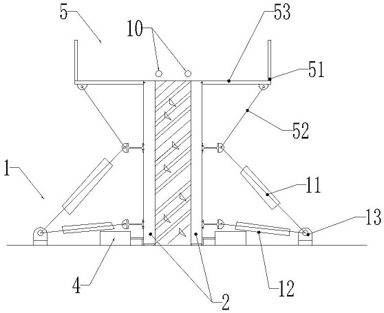
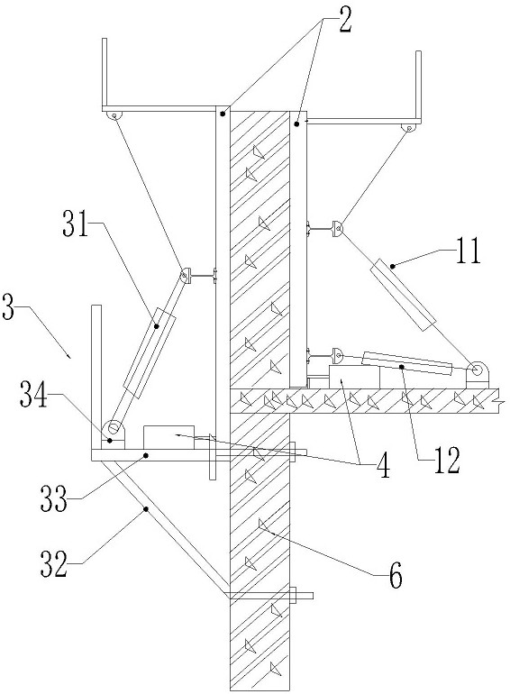
[0095] Such as Figure 1-11 As shown, the formwork system for building cast-in-place shear walls and infill walls includes formwork 2, first formwork support mechanism 1, second formwork support mechanism 3, concrete pouring platform mechanism 5, third formwork support mechanism 8, formwork Position monitoring mechanism 4, template verticality monitoring mechanism 9 and template cleaning mechanism.

[0096] Wherein, the first formwork support mechanism 1 is fixedly installed on the horizontal cast-in-place slab of the floor, and is used for supporting and positioning the formwork 2 on the horizontal cast-in-place slab of the floor.

[0097] The second template support mechanism 3 is fixedly installed on the outer wall of the vertical wall 6 for supporting and positioning the template 2; the vertical wall 6 is generally an outer wall.

[0098] The concrete pouring platform mechanism 5 is fixed on the upper end of the formwork 2, and is used for walking and operating standing o...


PUM


Abstract

The invention relates to a formwork system for a building cast-in-place shear wall and a filler wall and a construction method. The formwork system comprises a formwork, a first formwork supporting mechanism, a second formwork supporting mechanism, a third formwork supporting mechanism, a formwork position monitoring mechanism and a formwork perpendicularity monitoring mechanism, wherein the first formwork supporting mechanism is used for supporting and adjusting the formwork located on a floor horizontal cast-in-place slab; the second formwork supporting mechanism is used for supporting and adjusting the formwork located on the outer side of the floor horizontal cast-in-place slab; the third formwork supporting mechanism is used for supporting the formwork forming a door opening and a window opening; the formwork position monitoring mechanism is used for monitoring the position of the formwork; and the formwork perpendicularity monitoring mechanism is used for monitoring the perpendicularity of the formwork. The formwork splicing quality and efficiency are improved, one-time splicing and repeated multi-floor turnover use are achieved, and the splicing labor and mechanical cost is reduced; and by applying the construction method, the cost can be reduced, and the construction period can be shortened.

Description

technical field [0001] The invention relates to the field of building construction, in particular to a formwork system and a construction method for building cast-in-place shear walls and filling walls. Background technique [0002] At present, China is affected by the development trend of land resources and buildings, and the number of high-rise and super high-rise shear wall structure buildings and prefabricated buildings of laminated panels is increasing; the formwork system in the traditional construction method has less turnover times, is easy to deform, and is affected by wood. Resource shortage, non-recyclable and other constraints, the cost continues to increase, and the removal of the shear wall formwork can only be carried out after the cast-in-place slab concrete is poured, and the demolition is affected by obstacles such as the supporting steel pipes at the bottom of the cast-in-place slab formwork, so the demolition and handling efficiency is very low , The labo...

Claims


Application Information

Patent Timeline
Patent Type & Authority Applications(China)
IPC IPC(8): E04G11/02E04G11/08E04G17/14E04G17/00E04G17/16E04B2/84
CPCE04B2/84E04G11/02E04G11/08E04G11/085E04G17/002E04G17/14E04G17/16
Inventor 李洪宾
Owner 李洪宾
Why Eureka
Try Eureka