Stable column type weighing sensor structure

A load cell and column technology, applied in the field of load cells, can solve the problems of poor lateral force resistance, poor overload resistance, and poor anti-overturning ability, and achieve good lateral force resistance and overload resistance. The effect of strong and anti-dumping ability

Pending Publication Date: 2021-05-11
航天南洋(浙江)科技有限公司
View PDF1 Cites 0 Cited by
  • Summary
  • Abstract
  • Description
  • Claims
  • Application Information

AI Technical Summary

Problems solved by technology

[0005] However, the structure of the above-mentioned column load cell still has the following disadvantages: poor a

Method used


Image

  • Stable column type weighing sensor structure
  • Stable column type weighing sensor structure
  • Stable column type weighing sensor structure

Examples


Embodiment 1

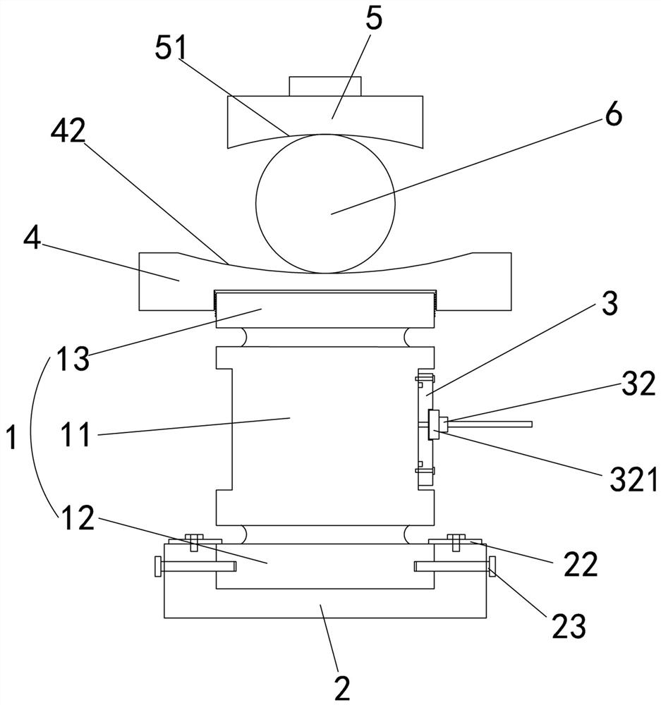
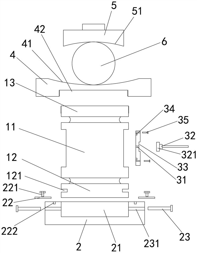
[0030] Embodiment one: if Figures 1 to 4 As shown, it is only one of the embodiments of the present invention, a stable column load cell structure, including an elastic body 1, a base 2 for supporting the elastic body 1, and a base for connecting the elastic body 1 The outlet plate 3, the expansion piece 4 set on the side of the elastic body 1 far away from the base 2, the pressure head 5 set on the side of the expansion piece 4 away from the base 2, and the expansion piece 5 set on the side of the expansion The steel ball 6 between the piece 4 and the indenter 5, the elastic body 1 includes a main body 11, a first connecting piece 12 and a second connecting piece 13, and the side of the first connecting piece 12 is provided with a first plug hole 121, the base 2 is provided with a fixing hole 21 for facilitating the insertion of the first connecting piece 12, a limiting plate 22 for connecting with the first connecting piece 12, and a limiting plate 22 for connecting with th...

Embodiment 2

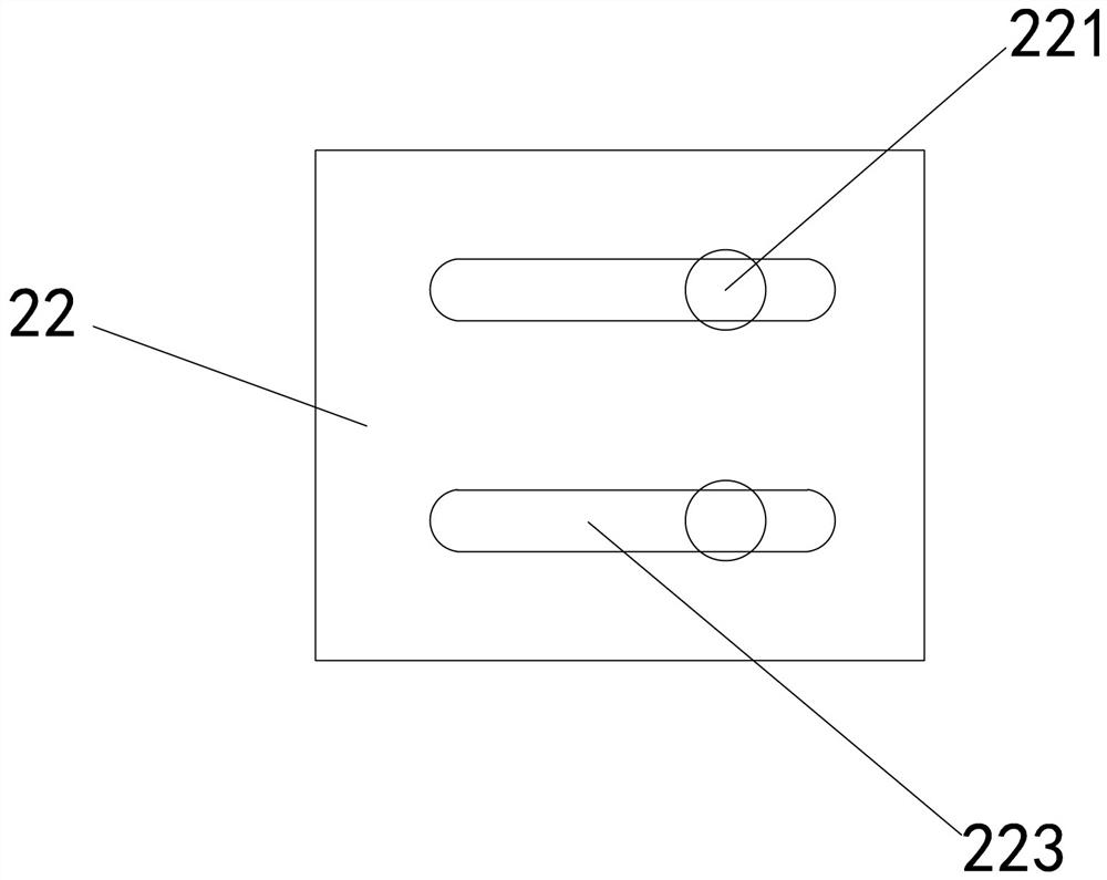
[0041] Embodiment two, still as Figures 1 to 4 As shown, it is only one of the embodiments of the present invention. On the basis of Embodiment 1, in a stable column type load cell structure of the present invention, the limiting plate 22 is provided with a convenient fixing bolt 221 passes through and slides the chute 223. That is to say, the fixing bolt 221 can slide in the chute 223, and when the fixing bolt 221 is unscrewed but not unscrewed, the position of the limiting plate 22 can be adjusted so that the limiting plate 22 can slide well and extend to The upper surface of the first connecting piece 12 completes the function of limiting the first connecting piece 12 .

[0042] Moreover, the strain gauge is a blind hole type or a through hole type, which is convenient to obtain the weight change above the device when straining.

[0043] In addition, a first external thread is provided on the outside of the second connecting piece 13, and a first internal thread matching...


PUM


Abstract

The invention provides a stable column-type weighing sensor structure, and relates to the technical field of load-bearing sensors. The stable column type weighing sensor structure comprises an elastic body, a base, a wire outlet plate, an expansion piece, a pressure head and a steel ball, the elastic body comprises a main body, a first connecting piece and a second connecting piece, and the side edge of the first connecting piece is provided with a first insertion hole; the base is provided with a fixing hole, a limiting plate, an anti-rotation pin, a fixing bolt, a first bolt hole and an anti-rotation pin hole, the wire outlet plate is provided with a cable, a cable hole and a cable connector piece, the side, close to the wire outlet plate, of the cable connector piece is provided with a connector, and the wire outlet plate is provided with a second insertion hole through which the connector can penetrate conveniently; and the side, close to the second connecting piece, of the expansion piece is provided with a connecting hole for facilitating insertion of the second connecting piece. The stable column type weighing sensor structure is simple in structure, small in size, light in weight, high in precision, high in toppling resistance, good in self-resetting effect, good in lateral force resistance and high in overload resistance.

Description

technical field [0001] The invention relates to the technical field of weighing sensors, [0002] In particular, the present invention relates to a stable column load cell structure. Background technique [0003] At present, the market volume of load cells for electronic truck scales is huge, and electronic truck scales will be used in various pricing and trade settlements. Due to the fierce market competition and the harsh operating environment of electronic truck scales, the price and quality of weighing sensors for electronic truck scales are required to be relatively high. [0004] At present, the most widely used electronic truck scales in the domestic market are double-shear bridge-type load cells with steel balls, which are mainly composed of base, elastic body, elastic body and base fixing bolts, steel balls, and pressure heads. Due to the needs of its own elastic body deformation space and load-bearing capacity, the sensor needs to be made into a large volume, whi...

Claims


Application Information

Patent Timeline
IPC IPC(8): G01G19/02G01G21/08G01G23/00
CPCG01G19/021G01G21/08G01G23/00G01G23/005
Inventor 孙亮亮嵇治刚
Owner 航天南洋(浙江)科技有限公司
Why Eureka
Try Eureka