Optical acceleration sensor and acceleration sensor system

An acceleration sensor and optical technology, applied in the field of optical sensors, can solve the problems of optical fiber becoming brittle and unable to measure high-frequency vibration signals

Pending Publication Date: 2021-05-11
宁波正业自动化科技有限公司
View PDF0 Cites 1 Cited by
  • Summary
  • Abstract
  • Description
  • Claims
  • Application Information

AI Technical Summary

Problems solved by technology

[0003] The problem solved by the invention is that the fiber Bragg g...

Method used


Image

  • Optical acceleration sensor and acceleration sensor system
  • Optical acceleration sensor and acceleration sensor system
  • Optical acceleration sensor and acceleration sensor system

Examples


Embodiment Construction

[0038] The existing mainstream optical acceleration sensor technologies include fiber Bragg grating technology and Fabry-Perot optical resonant cavity technology.

[0039] Fiber Bragg grating technology is to make Bragg gratings on ordinary optical fibers. There are generally two processes for this kind of production, one is laser interference method, the other is mask method, but no matter which method is used, the coating layer needs to be stripped. However, the optical fiber itself with the coating layer stripped off is brittle and easy to break, and is prone to fatigue or even breakage under long-term vibration. Therefore, not only the service life is too short, but also high-frequency vibration signals cannot be measured.

[0040] In addition, when the bending radius of the optical fiber of the optical fiber sensor is too small, there is basically no signal output; therefore, when it is packaged into a sensor, it must be at least 10 times the fiber diameter as the bending ...


PUM


Abstract

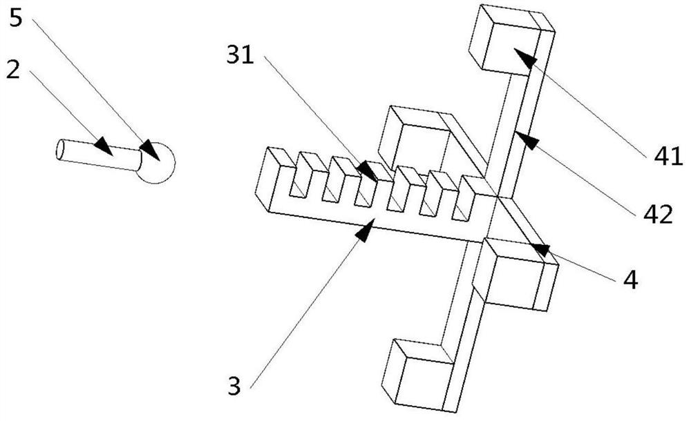
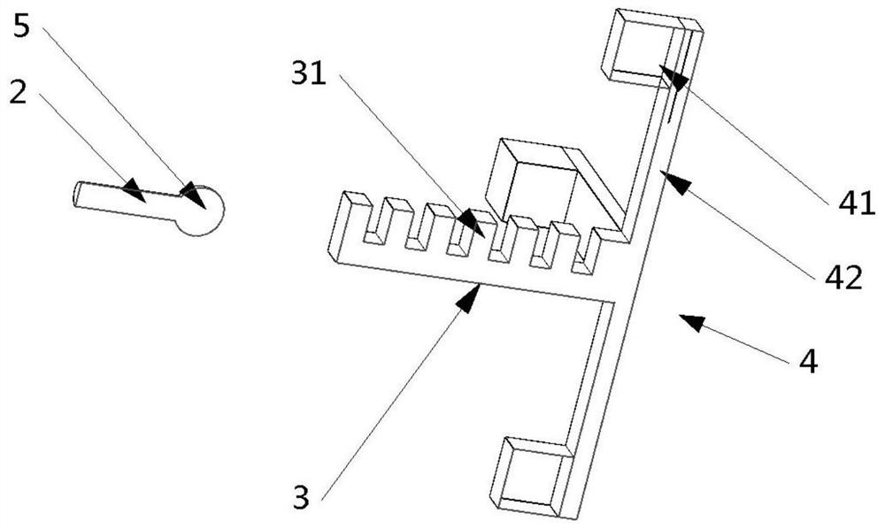
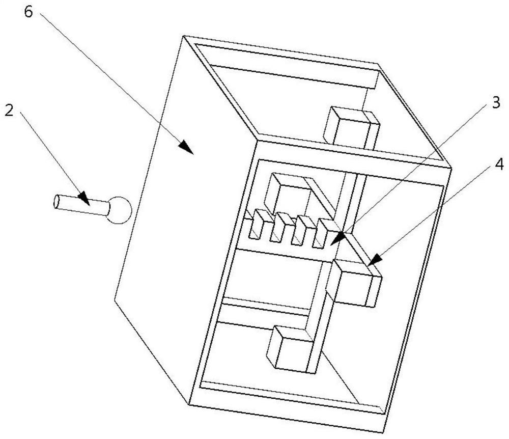
The present invention provides an optical acceleration sensor and an acceleration sensor system. The optical acceleration sensor comprises: a conductive optical fiber, wherein light waves are conducted in the conductive optical fiber; a semiconductor structure, wherein Bragg grating is etched on the semiconductor structure, and the semiconductor structure is aligned with the conductive optical fiber, modulates incident light waves, and then reflects back the modulated incident light waves to the conductive optical fiber; and a vibration assembly connected with the semiconductor structure and used for sensing the vibration of a measured object and transmitting the vibration to the Bragg grating. According to the invention, the semiconductor structure and the conductive optical fiber are arranged in a separated mode, and when packaging is needed, the semiconductor structure is directly packaged, so that the problems that the bending radius of the optical fiber is too small, and the size of the packaged sensor is too large are solved; and the semiconductor structure is more stable, so that the problems that the Bragg fiber grating is fragile and fragile, and high-frequency vibration signals cannot be measured are solved.

Description

technical field [0001] The invention relates to the technical field of optical sensors, in particular to an optical acceleration sensor and an acceleration sensor system. Background technique [0002] The existing mainstream optical acceleration sensor technologies include fiber Bragg grating technology and Fabry-Perot optical resonant cavity technology. The former is mainly to modulate the core periodic refractive index of the fiber on the ordinary fiber. This method is easy to make the fiber brittle, and there are defects such as fatigue or even fracture of the fiber under long-term vibration, and the inability to measure high-frequency vibration signals. In addition, in the package When forming a sensor, due to the estimation of the bending radius of the optical fiber so as not to attenuate the optical signal, the packaged sensor will not be small in size, so it is not suitable for environments with harsh internal space dimensions. The change of the latter optical signal...

Claims


Application Information

Patent Timeline
IPC IPC(8): G01P15/03
CPCG01P15/03
Inventor 吴迅奇朱洁琼
Owner 宁波正业自动化科技有限公司
Why Eureka
Try Eureka