Eureka AIR delivers breakthrough ideas for toughest innovation challenges, trusted by R&D personnel around the world.

Diffractive optical element and system for generating focused flat-topped spot light beam

A technology of diffractive optical elements and flat-top light spots, used in optical elements, optics, instruments, etc.

Active Publication Date: 2021-05-11
北京润和微光科技有限公司
View PDF5 Cites 5 Cited by
  • Summary
  • Abstract
  • Description
  • Claims
  • Application Information

AI Technical Summary

Problems solved by technology

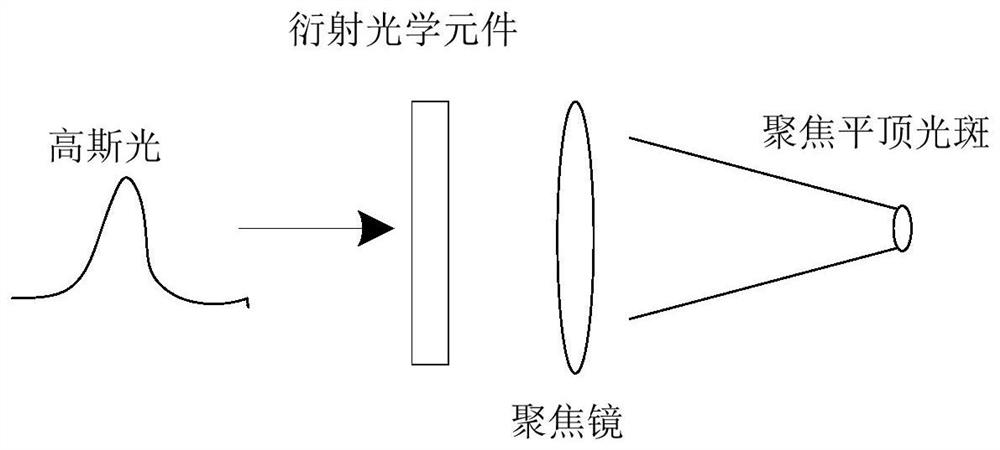
[0004] The purpose of the embodiments of the present invention is to provide a diffractive optical element and a system for generating a focused flat-top spot beam, so as to solve the problems existing in the existing Gaussian focused spot conversion in terms of energy utilization rate, difficulty in component preparation, and difficulty in adjustment, etc.

Method used


Image

  • Diffractive optical element and system for generating focused flat-topped spot light beam
  • Diffractive optical element and system for generating focused flat-topped spot light beam
  • Diffractive optical element and system for generating focused flat-topped spot light beam

Examples


Embodiment Construction

[0030] The implementation of the present invention will be illustrated by specific specific examples below, and those skilled in the art can easily understand other advantages and effects of the present invention from the contents disclosed in this specification.

[0031] In the following description, for purposes of illustration rather than limitation, specific details, such as specific system architectures, interfaces, and techniques, are set forth in order to provide a thorough understanding of the present invention. It will be apparent, however, to one skilled in the art that the invention may be practiced in other embodiments without these specific details. In other instances, detailed descriptions of well-known systems, circuits, and methods are omitted so as not to obscure the description of the present invention with unnecessary detail.

[0032] In describing the present invention, it should be understood that the terms "center", "longitudinal", "transverse", "upper", ...


PUM


Abstract

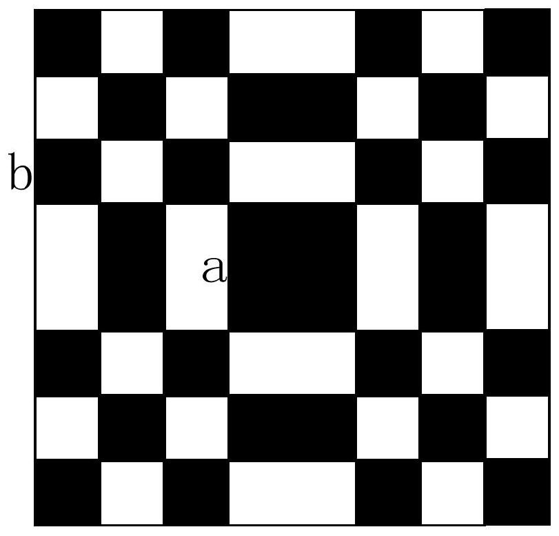
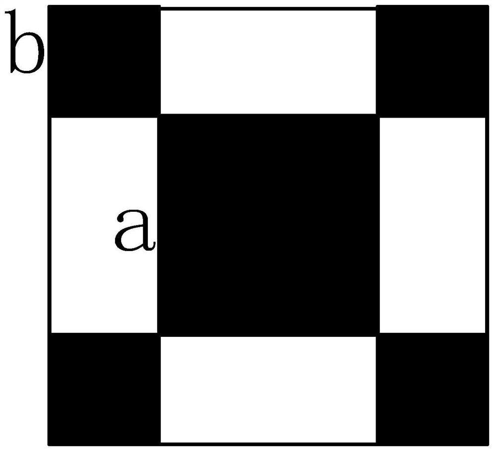
An embodiment of the invention discloses a diffractive optical element and a system for generating a focused flat-topped light spot beam. The diffractive optical element is used for generating the focused flat-topped light spot through diffraction and focusing of a focusing mirror when Gaussian light is incident, and comprises a Gaussian light receiving module and a phase modulation module, wherein the Gaussian light receiving module is used for receiving the Gaussian light; the phase modulation module is used for carrying out binarization phase modulation of sinc function beam splitting on the Gaussian light, the modulation phase of a modulation area of the phase modulation module is pi, and the modulation phase of a non-modulation area of the phase modulation module is 0; and the modulation area comprises a rectangle with the side length a and b and a square with the side length b, a is equal to 2w, b is equal to w, and w is the size of an incident light spot. The novel diffractive optical element is adopted for shaping, the size of the flat-topped focusing light spot is more accurately controlled, Gaussian beam incidence generates different phase differences through phase modulation of the diffractive optical element, and therefore an ideal flat-topped beam is obtained in a focusing plane.

Description

technical field [0001] The embodiments of the present invention relate to the technical field of optical equipment, and in particular to a diffractive optical element and a system for generating a focused top-hat spot beam. Background technique [0002] At present, in the laser micromachining industry, especially in applications such as laser lift-off, laser annealing, and laser solar panel scribing, traditional laser processing only relies on the Gaussian focused spot obtained by the focusing system, with high intermediate energy and edge energy. Low, in the process of processing, it often occurs that the middle area is overheated and over-processed, while the edge area is under-processed. Therefore, the focus flat-top spot distribution has increasingly become a processing bottleneck in related industries. [0003] At present, the main methods for converting Gaussian focus spot into flat-top focus spot include: aspheric lens, microlens array, aperture method, etc. However...

Claims


Application Information

Patent Timeline
IPC IPC(8): G02B5/32G02B27/09
CPCG02B5/32G02B27/0944G02B27/0927
Inventor 彭亦超
Owner 北京润和微光科技有限公司
Why Eureka
Eureka Blog
Learn More