
Low-voltage-drop Schottky rectifier tube

A rectifier, low-voltage drop technology, applied in electrical components, circuits, semiconductor devices, etc., can solve problems affecting the forward conduction current of Schottky rectifiers, large forward voltage drop, poor performance of Schottky rectifiers, etc. , to achieve the effect of improving the weakening effect, reducing the forward voltage and increasing the forward current.

Inactive Publication Date: 2021-05-11
东莞市中之电子科技有限公司
View PDF4 Cites 0 Cited by
  • Summary
  • Abstract
  • Description
  • Claims
  • Application Information

AI Technical Summary

Problems solved by technology

[0003] When a forward voltage is applied to the Schottky rectifier, the Schottky barrier between the metal and the semiconductor can form a conduction effect, but there is still a non-negligible internal electric field at the Schottky barrier, forming a large The forward voltage drop affects the forward conduction current of the Schottky rectifier, and the performance of the Schottky rectifier is not good

Method used


Image

  • Low-voltage-drop Schottky rectifier tube

Examples


Embodiment Construction

[0020] In order to further understand the features, technical means, and specific objectives and functions achieved by the present invention, the present invention will be further described in detail below in conjunction with the accompanying drawings and specific embodiments.

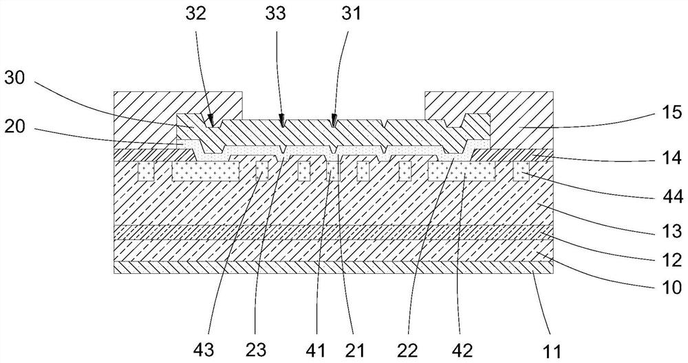
[0021] refer to figure 1 .

[0022] The embodiment of the present invention discloses a low-voltage drop Schottky rectifier, which includes an n-type substrate 10, a cathode metal layer 11 is arranged under the n-type substrate 10, and n-type buffer layers are sequentially stacked on the n-type substrate 10 along the longitudinal direction. Layer 12 and n-type drift layer 13, the n-type drift layer 13 is provided with a Schottky barrier metal layer 20 and an annular first passivation layer 14, and the center of the annular first passivation layer 14 is formed with a Schottky The opening of the base barrier metal layer 20, the edge of the Schottky barrier metal layer 20 is stacked on the first passivat...


PUM


Abstract

The invention provides a low-voltage-drop Schottky rectifier tube which comprises an n-type substrate, a cathode metal layer is arranged below the n-type substrate, an n-type buffer layer and an n-type drift layer are sequentially stacked on the n-type substrate, a Schottky barrier metal layer and an annular first passivation layer are arranged on the n-type drift layer, and an anode metal layer is arranged on the Schottky barrier metal layer. An annular second passivation layer is arranged on the anode metal layer; a first p-type embedded layer, a plurality of second p-type embedded layers and a plurality of third p-type embedded layers which are not in contact with one another are arranged in the n-type drift layer; the Schottky barrier metal layer is internally provided with a first lower convex part connected to the first p-type embedded layer, and the Schottky barrier metal layer is internally provided with a plurality of second lower convex parts connected to the second p-type embedded layers respectively. According to the invention, a plurality of p-type embedded layers are arranged in the n-type drift layer, the forward voltage drop is reduced, and the Schottky barrier metal layer is provided with a structure which is partially arched upwards, so that the forward conduction current can be improved.

Description

technical field [0001] The invention relates to a Schottky rectifier, and specifically discloses a Schottky rectifier with low pressure drop. Background technique [0002] Schottky rectifiers, also known as Schottky diodes, are made by contacting metal and semiconductor to form a metal-semiconductor junction. It has excellent performance of low power consumption and ultra-high speed. [0003] When a forward voltage is applied to the Schottky rectifier, the Schottky barrier between the metal and the semiconductor can form a conduction effect, but there is still a non-negligible internal electric field at the Schottky barrier, forming a large The forward voltage drop affects the forward conduction current of the Schottky rectifier, and the performance of the Schottky rectifier is not good. Contents of the invention [0004] Based on this, it is necessary to address the problems in the prior art to provide a low-drop Schottky rectifier with low forward voltage and large forw...

Claims


Application Information

Patent Timeline
Patent Type & Authority Applications(China)
IPC IPC(8): H01L29/872H01L29/47H01L29/06
CPCH01L29/872H01L29/47H01L29/0619
Inventor 王建云
Owner 东莞市中之电子科技有限公司
Learn More