
Multi-frequency antenna, radiation unit assembly, radiation unit installation structure and fixed seat

A technology of radiation unit and installation structure, applied in the field of communication, can solve the problems of scratching, affecting the performance of the antenna, winding, etc.

Pending Publication Date: 2021-05-11
COMBA TELECOM TECH (GUANGZHOU) CO LTD +1
View PDF0 Cites 0 Cited by
  • Summary
  • Abstract
  • Description
  • Claims
  • Application Information

AI Technical Summary

Problems solved by technology

In order to improve the space utilization rate of the antenna, in the existing combination of radiating elements, a smaller radiating element is nested into another radiating element for assembly and welding. After the welding is completed, the two radiating elements are mutually movable, which is easy Collision with each other causes scratches, entanglement, etc., which ultimately affects the performance of the antenna

Method used


Image

  • Multi-frequency antenna, radiation unit assembly, radiation unit installation structure and fixed seat
  • Multi-frequency antenna, radiation unit assembly, radiation unit installation structure and fixed seat
  • Multi-frequency antenna, radiation unit assembly, radiation unit installation structure and fixed seat

Examples


Embodiment Construction

[0034] Embodiments of the present invention will be described in more detail below with reference to the accompanying drawings. Although certain embodiments of the invention are shown in the drawings, it should be understood that the invention may be embodied in various forms and should not be construed as limited to the embodiments set forth herein; A more thorough and complete understanding of the present invention. It should be understood that the drawings and embodiments of the present invention are for exemplary purposes only, and are not intended to limit the protection scope of the present invention.

[0035] As used herein, the term "comprise" and its variations are open-ended, ie "including but not limited to". The term "connected" may be directly connected or indirectly connected through intermediate parts (elements). The term "one embodiment" means "at least one embodiment"; the term "another embodiment" means "at least one further embodiment"; the term "some embo...


PUM


Abstract

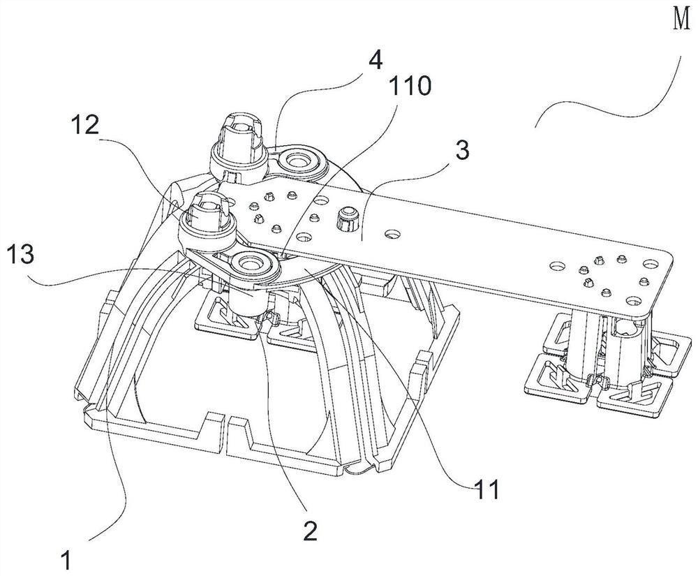
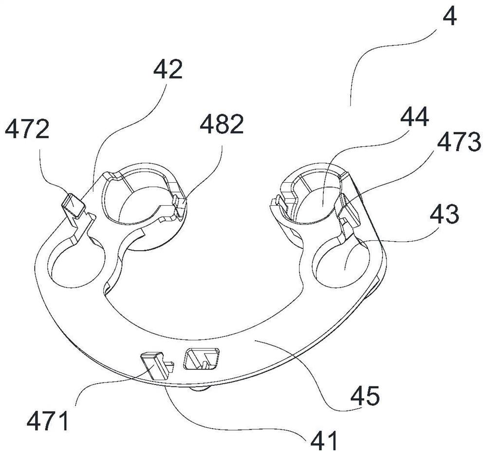
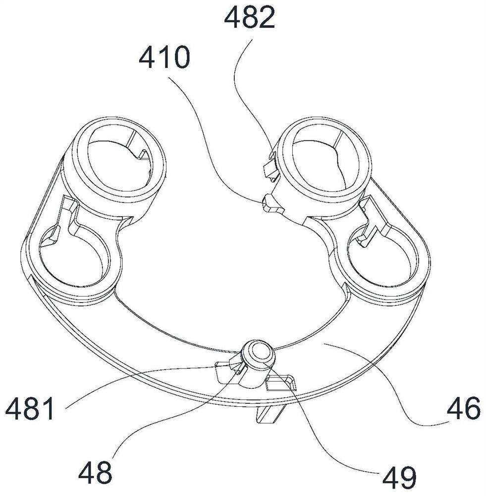
The invention provides a multi-frequency antenna, a radiation unit assembly, a radiation unit mounting structure and a fixing seat. The radiation unit mounting structure comprises a low-frequency radiation unit, a high-frequency radiation unit, a feed substrate and a fixed seat, the fixed seat comprises a strip-shaped waist part attached to the bottom surface of the base and two armrest parts formed by extending from the two ends of the waist part, and each armrest part is provided with an avoiding hole corresponding to one mounting column; a feed hole is arranged corresponding to one of the feed columns, the top surface of the fixed seat is clamped with the base, and the bottom surface of the fixed seat clamps the feed substrate. The radiation unit mounting structure can more stably fix a plurality of radiation units therein, and avoid mutual collision and scratch.

Description

technical field [0001] The present invention relates to the technical field of communication, in particular, the present invention relates to a multi-frequency antenna, a radiation unit assembly, a radiation unit installation structure and a fixing base. Background technique [0002] With the development of the communication industry, miniaturized, multi-band, and multi-standard base station antennas have increasingly become the mainstream antennas used in the communication industry. In the base station antenna structure, the radiation unit is the most important component, and its own quality and installation quality have a direct impact on the indicators of the entire antenna. In order to improve the space utilization rate of the antenna, in the existing combination of radiating elements, a smaller radiating element is nested into another radiating element for assembly and welding. After the welding is completed, the two radiating elements are mutually movable, which is eas...

Claims


Application Information

Patent Timeline
IPC IPC(8): H01Q1/36H01Q5/28H01Q15/14
CPCH01Q1/36H01Q15/14H01Q5/28
Inventor 刘永军管定金周金绿
Owner COMBA TELECOM TECH (GUANGZHOU) CO LTD
Learn More