Anti-toppling scarecrow for farmland
An anti-dumping and scarecrow technology, applied in applications, animal repellents, animal husbandry, etc., can solve the problem that scarecrows are easy to dump
- Summary
- Abstract
- Description
- Claims
- Application Information
AI Technical Summary
Problems solved by technology
Method used
Image

Examples
Embodiment 1
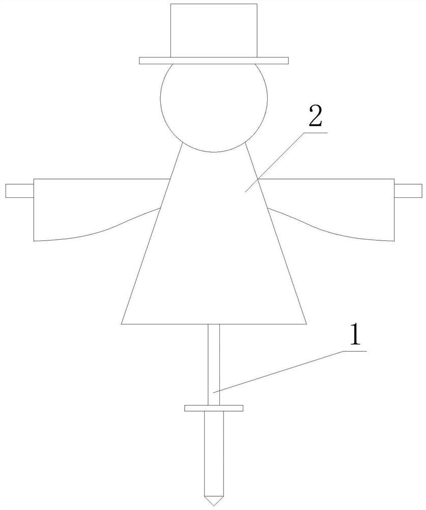
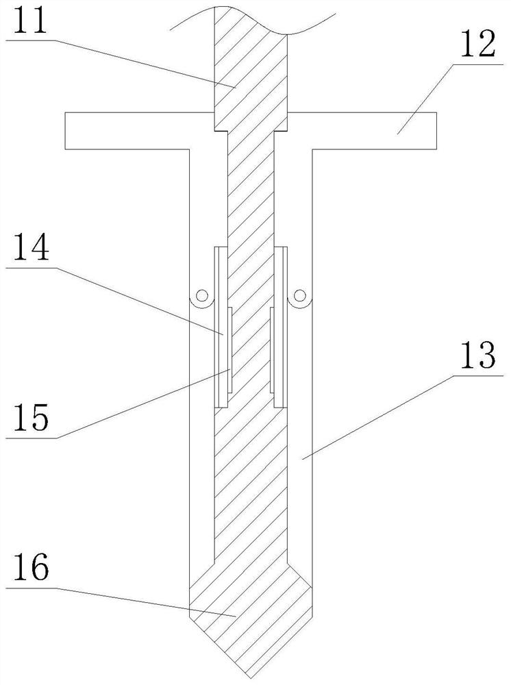
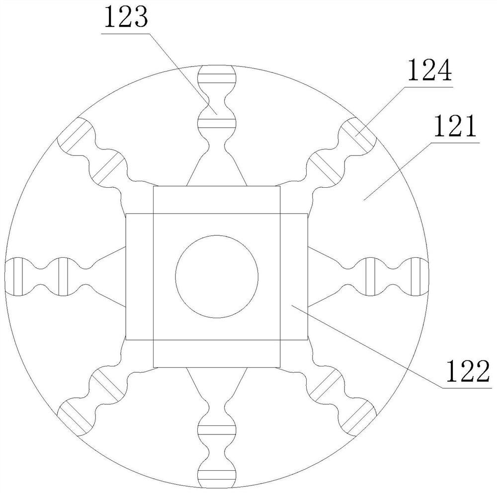
[0027] like figure 1 - Figure 4 As shown, the present invention provides an anti-dumping scarecrow for farmland, comprising a fixed rod 1, the upper end of the fixed rod 1 is fixedly connected with a straw frame body 2, the lower end of the fixed rod 1 is provided with an embedded rod 11, and the lower end of the embedded rod 11 is provided with There is an introduction block 16. The introduction block 16 and the embedded rod 11 are integrally designed. The side of the embedded rod 11 is provided with a sliding groove 14, and the lower end of the sliding groove 14 is provided with a clamping groove 15. The upper outer surface of the embedded rod 11 slides and clamps There is an adjustment pedal 12, the lower end of the adjustment pedal 12 is hingedly connected with a card slot 15, the inside of the adjustment pedal 12 is provided with a pressure plate 121 and a connecting foot 122, the pressure plate 121 and the connecting foot 122 are integral structure, and the lower end of...
Embodiment 2
[0030] like Figure 5 As shown, on the basis of Embodiment 1, the present invention provides a technical solution: the interior of the mud-embedded structure 124 is provided with a bead t1, and the bead t1 is symmetrically arranged on a wave-shaped plate, which is designed to increase the contact with mud and water. Area, the interior of the bead t1 is provided with a mud-embedding hole t3, and the edge of the bead t1 is provided with a differential pressure hole t2.
[0031] In this embodiment, through the design of the bead t1, the contact area with mud and water is increased, and through the intermolecular force, the force required by the present invention when tilting is further increased, and through the design of the differential pressure hole t2, The tension when passing through makes the inside of the differential pressure hole t2 form a sealed air cavity, so that the present invention generates a certain buoyancy when it is inclined, and is designed through the mud em...
Embodiment 3
[0033] like Image 6 As shown, on the basis of Embodiment 1, the present invention provides a technical solution: preferably, a No. 1 air cavity a1 is provided on one side of the inside of the sliding block 133, and the upper part of the No. 1 air cavity a1 is movably connected and tightly fitted. There is a3, the inner side of the sliding block 133 away from the first air chamber a1 is provided with a second air chamber a2, the interior of the second air chamber a2 is slidably connected and tightly fitted with a blocking block a3, and the middle of the blocking block a3 is provided with a The inclined cavity a5, the No. 1 air cavity a1 and the inclined cavity a5 are communicated with each other through the provided DC channel.
[0034] In this embodiment, through the design of a3 and the No. 1 air chamber a1, when a3 is squeezed, the pressure in the No. 1 air chamber a1 increases and the inclined surface of the blocking block a3 is matched, so that the blocking block a3 is pu...
PUM
 Abstract
Description
Claims
Application Information
 - R&D
- Intellectual Property
- Life Sciences
- Materials
- Tech Scout
- Unparalleled Data Quality
- Higher Quality Content
- 60% Fewer Hallucinations
Browse by: Latest US Patents, China's latest patents, Technical Efficacy Thesaurus, Application Domain, Technology Topic, Popular Technical Reports.
© 2025 PatSnap. All rights reserved.Legal|Privacy policy|Modern Slavery Act Transparency Statement|Sitemap|About US| Contact US: help@patsnap.com