Vacuum source cooling system and cleaning equipment

A technology of cooling system and vacuum source, applied in cleaning equipment, installation of electrical equipment, casing/cover/support, etc., can solve problems such as circuit board damage and heat generation

Pending Publication Date: 2021-05-14
SUZHOU CHO ELECTRIC APPLIANCE CO LTD
View PDF0 Cites 1 Cited by
  • Summary
  • Abstract
  • Description
  • Claims
  • Application Information

AI Technical Summary

Problems solved by technology

[0002] When the vacuum cleaner is working, the circuit board of the motor will heat up due to long-term work, so it is necessary to cool down the motor when the vacuum cleaner is working. The cooling system f

Method used


Image

  • Vacuum source cooling system and cleaning equipment
  • Vacuum source cooling system and cleaning equipment
  • Vacuum source cooling system and cleaning equipment

Examples


Embodiment Construction

[0031] The technical solutions in the embodiments of the present invention will be clearly and completely described below. Obviously, the described embodiments are only some of the embodiments of the present invention, rather than all of them; based on the embodiments of the present invention, those skilled in the art All other embodiments obtained by persons of ordinary skill without creative efforts fall within the protection scope of the present invention.

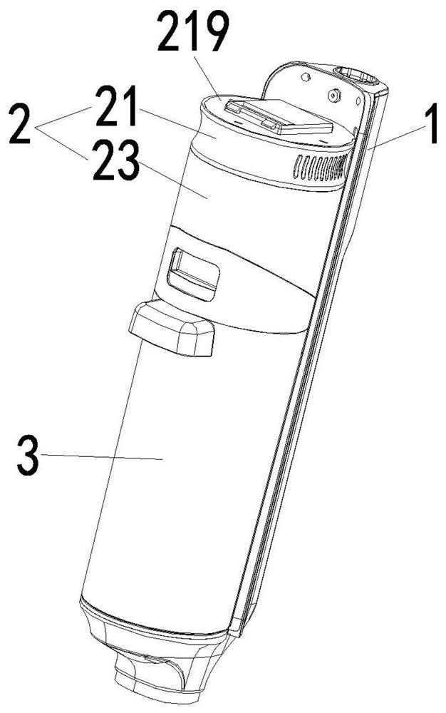
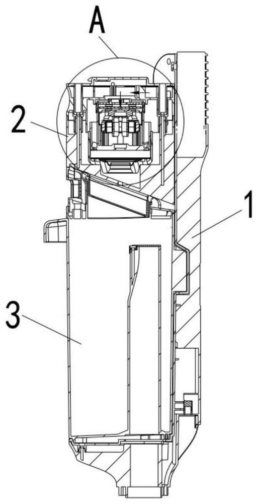
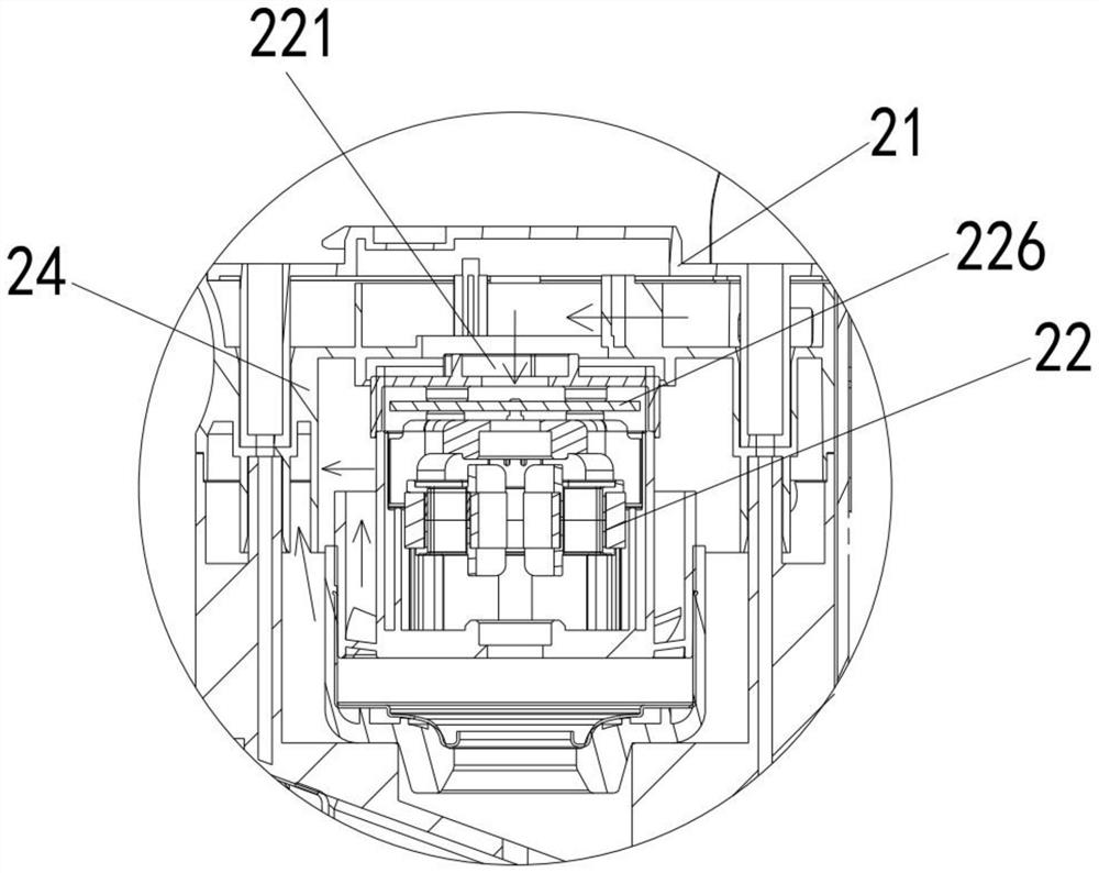
[0032] see Figure 1-14 , the vacuum source cooling system of the present invention includes the air guide channel air inlet 121 arranged on the frame 1, the air guide channel 12 arranged in the frame 1, and the cover plate 11 arranged on the frame 1 which are connected in sequence. The air guide channel air outlet 122 on the top, the first air guide hole 211 arranged on the side of the motor upper cover 21, the second air guide hole 212 arranged at the center of the inner cavity bottom of the motor upper cover 21, and ...


PUM

PropertyMeasurementUnit
Heightaaaaaaaaaa

Abstract

The invention discloses a vacuum source cooling system and cleaning equipment. The vacuum source cooling system comprises an air guide channel air inlet arranged on a rack, an air guide channel arranged in the rack, an air guide channel air outlet arranged on a cover plate of the rack, a first air guide hole arranged at the side part of an upper cover of a motor, a second air guide hole arranged in the upper cover of the motor, an air inlet channel arranged on the side wall of the motor main body, a main airflow inlet hole arranged at the bottom of the motor main body, and a first main airflow exhaust port arranged on the side wall of the motor main body whichare communicated in sequence, wherein the lowest point of the air inlet hole of the air guide channel on the rack is at least flush with the lowest point of the air guide channel in the rack, and the lowest point of the air outlet hole of the air guide channel in the rack cover plate is higher than that of the air guide channel in the rack. According to the invention, the motor main body can be continuously cooled, and the air flow can be automatically discharged out of the vacuum source after being cooled, so that the safe operation of the motor main body is ensured.

Description

technical field [0001] The invention relates to the field of vacuum cleaners, in particular to a vacuum source cooling system capable of continuously cooling the main body of the motor to ensure the continuous operation of the vacuum cleaner; at the same time, the vacuum source can be automatically discharged after the air flow passes through the cooling, so as to ensure the safe operation of the main body of the motor and the vacuum source cooling system. equipment. Background technique [0002] When the vacuum cleaner is working, the circuit board of the motor will heat up due to long-term work, so it is necessary to cool down the motor when the vacuum cleaner is working. The cooling system for the motor of the existing vacuum cleaner is usually relatively simple, and the liquid in the environment is easy to enter To the circuit board of the motor, causing the circuit board to be damaged by water. [0003] To this end, we have developed a vacuum source cooling system and ...

Claims


Application Information

Patent Timeline
IPC IPC(8): A47L9/28H02K5/20H02K11/30
CPCA47L9/2889H02K5/20H02K11/30
Inventor 邹宗彬
Owner SUZHOU CHO ELECTRIC APPLIANCE CO LTD
Why Eureka
Try Eureka