Shoe sole cleaning machine

A sole cleaning machine and cleaning technology, which are applied to cleaning equipment, cleaning of boots and shoes, household cleaning devices, etc., can solve the problems of poor water absorption, unsanitary and unsightly appearance of water absorbing pads, and improve cleaning efficiency and cleaning effect. , the effect of dexterity

Active Publication Date: 2021-05-14
JIMEI UNIV
View PDF14 Cites 1 Cited by
  • Summary
  • Abstract
  • Description
  • Claims
  • Application Information

AI Technical Summary

Problems solved by technology

[0003] 1. The overall device is bulky and difficult to move, difficult to disassemble and assemble;
[0004] 2. The device needs an external power supply to provide a power source to work, and the installation and use places are limited;
[0005] 3. Cleaning brushes are always exposed, unhygienic and unsightly;
[0006] 4. The cleaning brush is driven by the belt to move horizontally on the working surface to wipe the soles, and the cleaning effect is not ideal;
[0007] 5. The cleaning brush is only suitable for removing sand and other particles, and the cleaning effect on sole attachments is not good;
[0008] 6. The water absorption of the water-absorbent pad is poor, and it is difficult to quickly absorb the moisture of the sole

Method used


Image

  • Shoe sole cleaning machine
  • Shoe sole cleaning machine
  • Shoe sole cleaning machine

Examples


Embodiment Construction

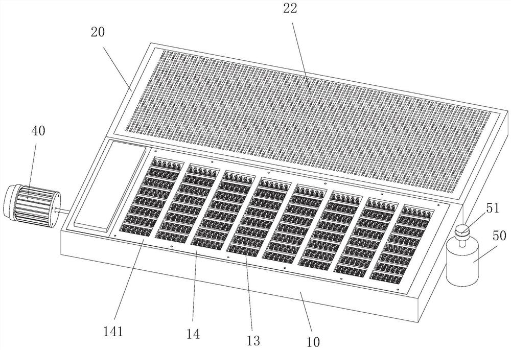
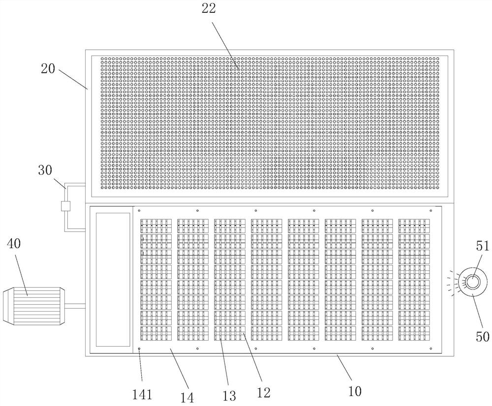
[0051] Such as Figure 1 to Figure 11 As shown, the present invention discloses a shoe sole cleaning machine, which includes a first water tank 10 and a second water tank 20 . The first water tank 10 and the second water tank 20 adopt a separate structure, and the two parts are spliced ​​together to make the mechanism into parts. The product structure is light and handy, convenient for packaging, handling and transportation, and convenient for disassembly and installation.

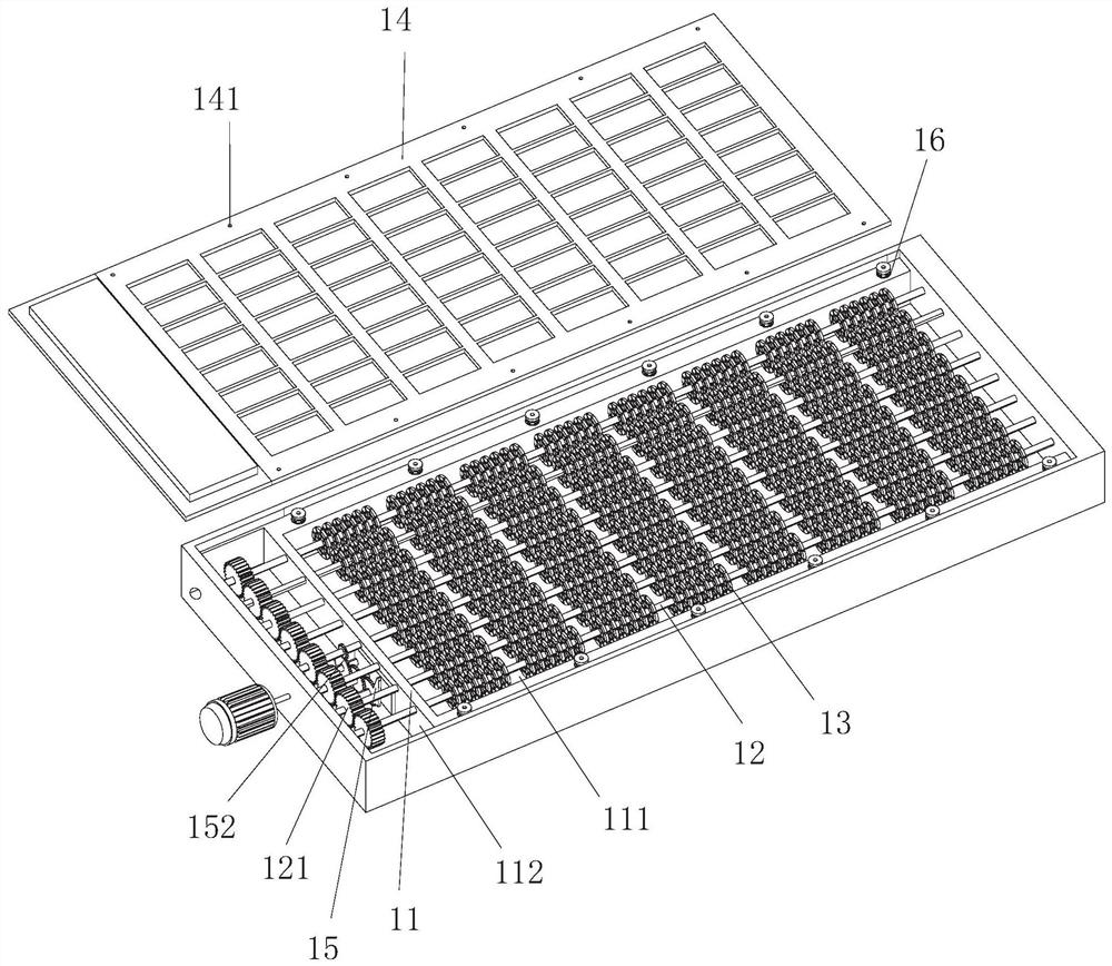
[0052] The first water tank 10 is positioned at the front of the whole device and plays the role of cleaning the soles. A frame 11 is provided in the first water tank 10 , and the frame 11 is mainly used to provide installation support for internal components of the first water tank 10 . Several rotating shafts 12 are arranged side by side on the frame 11, and several cleaning wheels are evenly arranged and installed on each rotating shaft 12. There is a circle of cleaning brushes 13 on the cleaning wheel...


PUM


Abstract

The invention discloses a shoe sole cleaning machine. The shoe sole cleaning machine comprises a first water tank and a second water tank which are separated, wherein the first water tank is provided with a frame, rotating shafts and cleaning wheels, and a driving rod and a change gear set are mounted on the frame; a pedal is further arranged in the first water tank in a liftable mode and located above the frame, the bottom of the pedal is connected with the upper end of the driving rod, longitudinal and transverse strips of the pedal avoid the cleaning wheels and are located above a gap between the cleaning wheels, the pedal moves downwards when being stressed and pressed downwards so as to enable cleaning brushes on the cleaning wheels to be exposed, meanwhile, the pedal presses the upper end of the driving rod downwards to enable the driving rod to rotate, the multiple rotating shafts rotate together through the change gear set and the transmission gear, and the cleaning brushes on the cleaning wheels are driven to rotate to conduct cleaning action; and a cover plate is arranged in the second water tank, water leakage holes are formed in the cover plate, and a water absorption pad is laid on the cover plate. The product is light and handy, has multiple power sources and is convenient to mount and dismount, the brush for cleaning is exposed only during use, sanitation and attractiveness are achieved, the cleaning effect is better, and the water absorption of the water absorption pad is good.

Description

technical field [0001] The invention relates to a shoe sole cleaning machine. Background technique [0002] At present, most of the shoe-shine structures on the market are designed for the uppers, and there are few devices for cleaning the soles. Although patents CN212281284U, CN211408956U and CN211381233U etc. have disclosed sole cleaning machines, it is not difficult to find out that there are many problems in these sole cleaning machines after careful analysis: [0003] 1. The overall device is bulky and difficult to move, difficult to disassemble and assemble; [0004] 2. The device needs an external power supply to provide a power source to work, and the installation and use places are limited; [0005] 3. Cleaning brushes are always exposed, unhygienic and unsightly; [0006] 4. The cleaning brush is driven by the belt to move horizontally on the working surface to wipe the soles, and the cleaning effect is not ideal; [0007] 5. The cleaning brush is only suitable...

Claims


Application Information

Patent Timeline
Patent Type & Authority Applications(China)
IPC IPC(8): A47L23/26
CPCA47L23/26
Inventor 王云超陈元钦陈世涵李楠沛胡志超李波郑东强
Owner JIMEI UNIV
Why Eureka
Try Eureka