
Fluid-driven control valve

A fluid-driven, control valve technology, applied in the field of medical equipment, can solve the problems of affecting liquid mixing, increasing liquid flow resistance, and unsatisfactory mixing effect, so as to increase the flow speed and promote the effect of liquid mixing

Active Publication Date: 2021-05-14
ZHUMADIAN VOCATIONAL & TECHN COLLEGE
View PDF13 Cites 0 Cited by
  • Summary
  • Abstract
  • Description
  • Claims
  • Application Information

AI Technical Summary

Problems solved by technology

[0002] Microfluidic technology uses the physical and chemical properties and scale effects of multiphase microfluidics to perform various operations in microchannels. Most of the current disk microfluidic chips are integral disc-shaped structures, and the microchannels are set in the disk body. The surface of the microchannel, the distance between the position of the microchannel and the center of the disc is invariable. When mixing various liquids, the purpose of mixing is achieved by adjusting the motor speed through the function of the microchannel. When adjusting the motor speed, because the motor has a certain inertia when rotating, As a result, the rotation speed adjustment has a certain hysteresis, and the rapid adjustment of the centrifugal force cannot be realized, resulting in an unsatisfactory mixing effect; and the microchannel mixing method requires a long mixing channel, and the mixing effect is easily affected by many factors. The mixing effect is difficult to control; and with the addition of different functions in the microchannel, the liquid flow resistance increases, which further affects the liquid mixing

Method used


Image

  • Fluid-driven control valve
  • Fluid-driven control valve
  • Fluid-driven control valve

Examples


Embodiment Construction

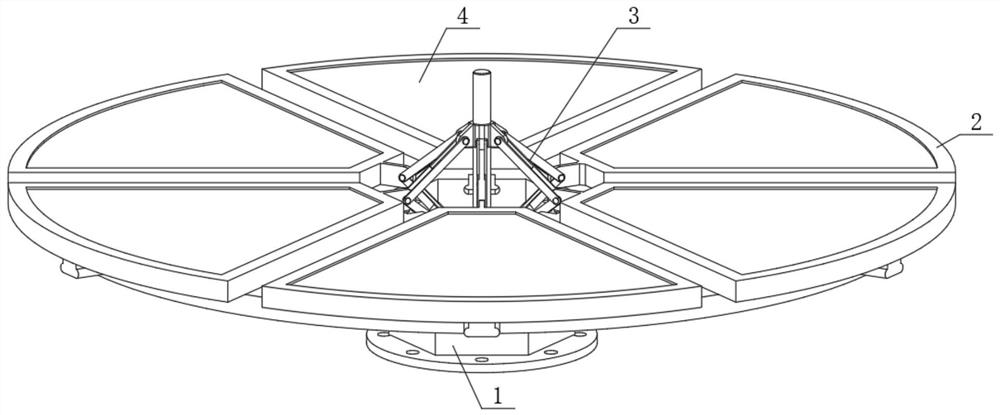
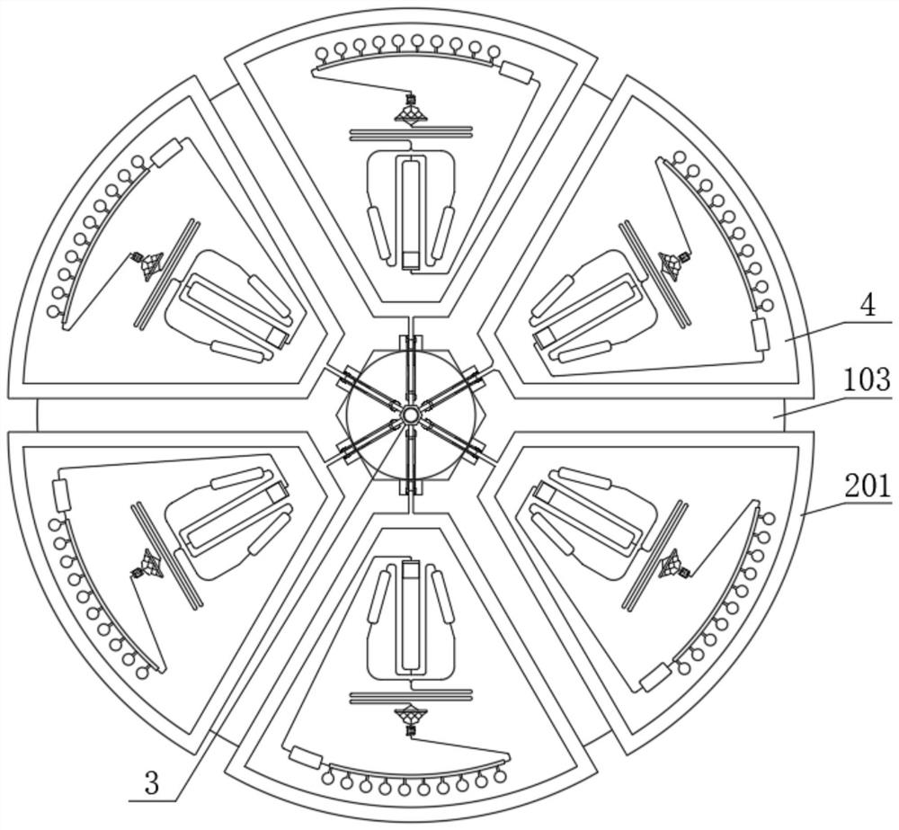
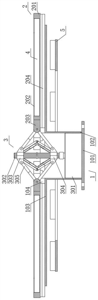
[0023]SeeFigure 1-2 , Fluid drive control valve, including support assembly 1, movable assembly 2, drive assembly 3, microfluid panel assembly 4, and magnetic assembly 5, such asimage 3 As shown, the support assembly 1 includes a support barrel 102 that is fixedly coupled with a support disk 103, and the top portion of the support disk 103 has a slide 104 in radially, the support disk 103 The bottom is fixedly connected to the drive disc 101, and the bottom portion of the drive disc 101 is fixed in its circumferential direction; the top portion of the support assembly 1 is connected to active assembly 2 along its circumferential activity, and the movable component 2 includes a movable board. 201, the bottom intermediate of the movable plate 201 is fixed to the slider 204, and the top of the movable plate 201 is opened, and the inner side of the movable plate 201 is fixedly connected to the connecting plate 203; the slider 204 slides Connected to the slot 104 of the top portion of th...


PUM


Abstract

The invention discloses a fluid driving control valve, and the valve comprises a supporting assembly, a movable assembly, a driving assembly, a micro-fluidic disc assembly and a magnetic assembly; the top of the supporting assembly is movably connected with the movable assembly in the circumferential direction of the supporting assembly, and the driving assembly is fixedly connected to the middle of the interior of the supporting assembly; the driving side of the driving assembly is hinged to the inner side of the movable assembly, the top of the movable assembly is connected with a micro-fluidic disc assembly in a clamped mode, and the lower portion of the supporting assembly is sleeved with a magnetic assembly. By arranging the movable assemblies, the multiple movable plates can be driven by the driving assembly to move in the radial direction of the top of the supporting disc, so the distance between the movable plates and the circle center and the distance between the micro-channel and the circle center are adjusted, and under the same rotating speed, the farther the distance from the circle center is, the larger the centrifugal force is; and the centrifugal force can be quickly adjusted at the same rotating speed, so different mixing effects are achieved.

Description

Technical field[0001]The present invention relates to the technical field of medical devices. Specifically, fluid drive control valve is specifically.Background technique[0002]Microfluidic technology is a multi-phase microfluidic physicochemical characteristic and scale effect, in a variety of operations in the microchannel, currently disc mostly a monolithic disc structure, microchannels are disposed in a disk The surface, the position of the microchannel and the center of the disc are not variable, and when a plurality of liquids are mixed, the control motor speed reaches the mixture, and when the motor rotation is regulated, it has a certain inertia when the motor rotates. The speed adjustment has a certain hysteresis, and cannot achieve rapid adjustment of the centrifugal force, resulting in the mixing effect is not ideal; and the mixing of the microchannels requires a longer hybrid passage, and the mixing effect is susceptible to more factors, It causes the mixing effect to be ...

Claims


Application Information

Patent Timeline
IPC IPC(8): B01F13/00
CPCB01F33/30B01F2101/2202
Inventor 晁红芬张瑞林刘磊何伟丽李汉青
Owner ZHUMADIAN VOCATIONAL & TECHN COLLEGE
Features
  • Generate Ideas
  • Intellectual Property
  • Life Sciences
  • Materials
  • Tech Scout
  • Unparalleled Data Quality
  • Higher Quality Content
  • 60% Fewer Hallucinations
Learn More