
LED display backlight source manufacturing process

A technology of LED display and manufacturing process, applied in the direction of manufacturing tools, instruments, optics, etc., can solve the problems of increasing scrap rate, increasing workload, affecting work efficiency, etc., to avoid multiple processing, improve work efficiency, and reduce workload Effect

Inactive Publication Date: 2021-05-14
合肥曾普蔬菜批发有限公司
View PDF0 Cites 0 Cited by
  • Summary
  • Abstract
  • Description
  • Claims
  • Application Information

AI Technical Summary

Problems solved by technology

[0003] However, the following problems exist in the production and processing of the light guide plate at present: most of the existing light guide plate manufacturing devices use alloy devices to limit and fix the light guide plate, but this type of device cannot effectively protect the light guide plate, so it is easy to Causes damage to the light guide plate during processing, thereby increasing the scrap rate; and when removing burrs, this type of device generally uses cutting processing to sequentially process the outer edge of the light guide plate, and cutting processing is easy to produce chips, if not removed in time, It will cause scratches on the light guide plate, thereby wasting costs, and the outer edge of the light guide plate cannot be processed synchronously, thereby increasing the workload and affecting work efficiency

Method used


Image

  • LED display backlight source manufacturing process
  • LED display backlight source manufacturing process
  • LED display backlight source manufacturing process

Examples


Embodiment Construction

[0030] In order to make the technical means, creative features, goals and effects achieved by the present invention easy to understand, the present invention will be further described below in conjunction with specific illustrations. It should be noted that, in the case of no conflict, the embodiments in the present application and the features in the embodiments can be combined with each other.

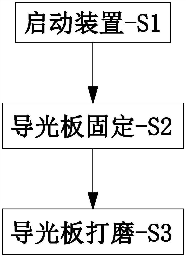
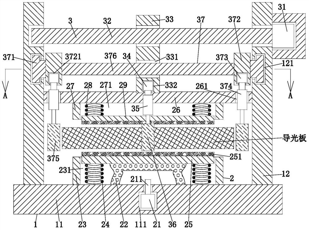
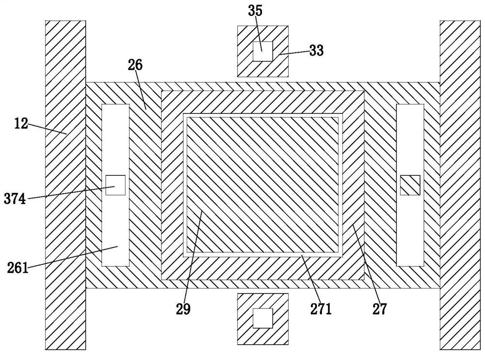
[0031] Such as Figure 1 to Figure 7 As shown, the present invention provides a LED display backlight manufacturing process. The LED display backlight manufacturing process adopts the following LED display backlight manufacturing device. The LED display backlight manufacturing device includes a frame 1, a fixing unit 2 and a polishing unit 3 , the inside of the frame 1 is provided with a fixing groove 111, the fixing unit 2 is arranged in the fixing groove 111, and the grinding unit 3 is installed on the inner side wall of the frame 1, wherein:

[0032] The frame 1 includes a base 1...


PUM


Abstract

The invention provides an LED display backlight source manufacturing process. The LED display backlight source manufacturing process adopts an LED displayer backlight source manufacturing device. The LED display backlight source manufacturing device comprises a machine frame, a fixing unit and a polishing unit, a fixing groove is formed in the machine frame, the fixing unit is arranged in the fixing groove, and the polishing unit is mounted on the inner side wall of the machine frame. The problems that most of existing light guide plate manufacturing devices adopt alloy devices to limit and fix light guide plates, but the devices cannot effectively protect the light guide plates, so that the light guide plates are prone to be damaged during machining, and the cost is wasted; and when the device is used for removing burrs, the outer edges of the light guide plates are generally processed in sequence in a cutting mode, and the outer edges of the light guide plates cannot be synchronously processed, so that the workload is increased, and the working efficiency is influenced are solved.

Description

technical field [0001] The invention relates to the technical field of LED display processing, in particular to a manufacturing process of an LED display backlight source. Background technique [0002] LED display backlight is a light source located behind the LED display. Its luminous effect will directly affect the visual effect of the LED display module. The backlight is mainly composed of a light source, a light guide plate, optical modules, and structural parts; the light guide plate is It is made of optical-grade acrylic sheet or PC sheet. The manufacturing methods mainly include injection molding, photolithography, laser engraving, sandblasting and single-point diamond processing. Injection molding is to fill the molten forming material into the In the closed mold, it is cooled and demoulded, and the light guide plate is initially formed. However, injection molding tends to leave burrs on the outer edge of the light guide plate. Therefore, for the later molding proces...

Claims


Application Information

Patent Timeline
Patent Type & Authority Applications(China)
IPC IPC(8): B24B9/14B24B27/00B24B41/06B24B47/00B24B47/16G02B6/00
CPCB24B9/14B24B9/146B24B27/0076B24B41/06B24B47/00B24B47/16G02B6/0013G02B6/0033G02B6/0065
Inventor 刘永春邢素华
Owner 合肥曾普蔬菜批发有限公司
Learn More