Automatic patching machining table for plywood
A technology for processing tables and plywood, applied in metal processing equipment, manufacturing tools, grinding skateboards, etc., can solve the problems of scar inspection omissions, time-consuming and labor-intensive, affecting appearance and quality, and achieve the effect of saving material loss and improving accuracy
- Summary
- Abstract
- Description
- Claims
- Application Information
AI Technical Summary
Problems solved by technology
Method used
Image

Examples
Embodiment 1
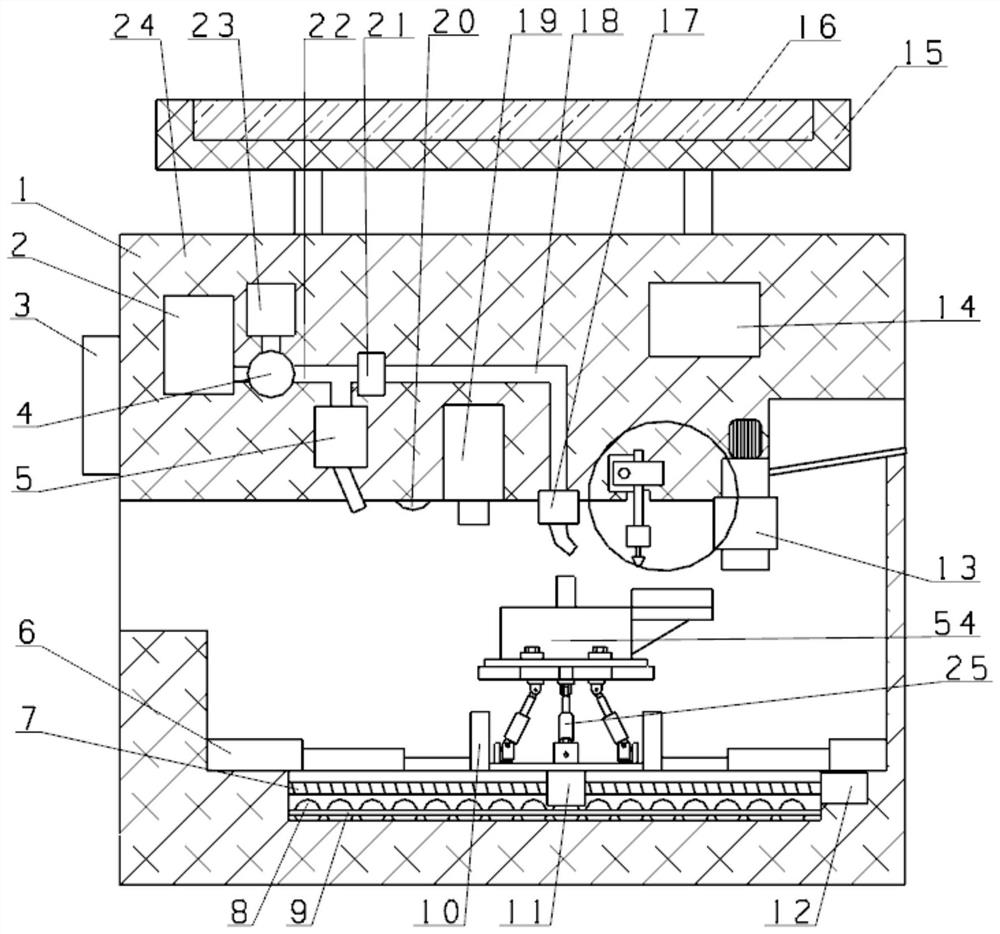
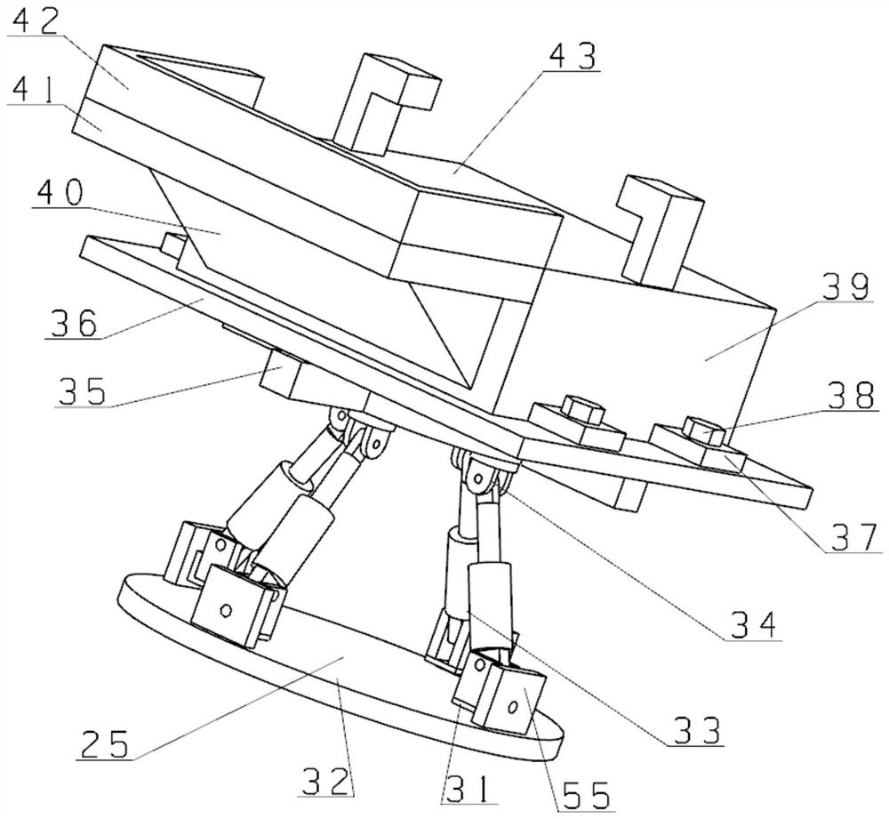
[0023] see Figure 1~Figure 6 As shown, a plywood automatic digging and mending processing platform includes a processing device 1, and the processing device 1 includes a cabinet 24, a filling module making mechanism 13 is arranged in the cabinet 24, and a first motor 12 is arranged on the cabinet 24, The first motor 12 is provided with a first screw 7, and the first screw 7 is threadedly connected with a moving block 11, and the moving block 11 is provided with an adjustment device 54, and the adjustment device 54 includes a posture adjustment device 25, The posture adjustment device 25 includes a base plate 32, which is fixedly connected to the moving block 11, a seat plate 55 is fixedly mounted on the base plate 32, and a first turret 31 is rotatably connected to the vertical seat plate 55. , the first turret 31 is rotatably connected with a hydraulic push rod 33, the hydraulic push rod 33 is connected with a second turret 34, and the second turret 34 is rotatably connected...
Embodiment 2
[0030] On the basis of embodiment one, refer to figure 1 , the moving block 11 is provided with a plurality of balls 8, the balls 8 are connected to the cabinet 24, and the balls 8 are connected to the cabinet 24 through the ball frame 9; the ball frame 9 fixes the balls 8, and the balls 8 reduce the moving block 11 wear and tear.
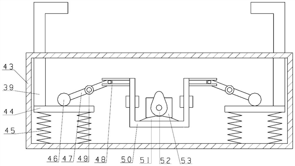
[0031] Working principle: in the process of use, the plywood is placed on the plywood box 43, through the second motor 53, the cam 52, the bump 51, the concave frame 50, the splint 48, the rotating rod 47, the fixed shaft 49, the heavy ball 46, The cooperation of horizontal plate 44, spring 45, splint box 43, press plate 39, press plate 39 moves down, plywood is pressed on the frame plate box 43, first motor 12 moves moving block 11 by first screw rod 7, and splint box 43 Move to the powder spraying head 5, while blowing air in the high-pressure air pump 2, mix the powder leaked from the phosphor powder hopper 23, blow the gas with phosphor to the...
PUM
 Abstract
Description
Claims
Application Information
PatSnap Eureka turns technology decisions into work you can execute. Powered by our Innovation Knowledge Graph, it runs expert workflows across engineering, life sciences, materials and intellectual property. Get your review-ready output in minutes.


