Internal profile production line

A production line and profile technology, which is applied in the direction of household components, household appliances, and other household appliances, can solve the problems of reduced yield, too long or too short, and high requirements for the length of the heating channel, so as to improve the bonding strength and improve the bonding strength. The effect of bonding strength

Pending Publication Date: 2021-05-14
杨圣育
0 Cites 0 Cited by

AI-Extracted Technical Summary

Problems solved by technology

[0003] However, because the bonding medium between the heat insulation strip and the metal frame is butyl rubber during processing, and butyl rubber is in the heating channel of the production line, if the channel is too long, the bonding strength on the two wings of the metal frame will decrease. When the channel is too short, the melting effect of butyl rubber is not good, and the metal frame and the heat insulation strip will be evenly bonded, whic...

Method used

The outlet of sheet metal roll 3 is flush with the entrance of squeeze roll 1, and between sheet metal roll 3 and squeeze roll 1, be provided with lifting roll 15 and lower pressure roll 16, sheet metal 17 is from sheet metal roll 3 After coming out, it goes around the top of the lifting roller 15 and the bottom of the lower pressing roller 16 successively, and enters the extrusion roller 1. The top of the lifting roller 15 is higher than the exit of the sheet metal roll 3, and the bottom of t...

Abstract

The invention relates to an internal profile production line. The interval profile production line comprises an extrusion roller, a heat insulation strip conveying roller and a metal sheet roller, the heat insulation strip conveying roller and the metal sheet roller are arranged on the upstream of the extrusion roller, a heating channel, a cooling channel, a straightening device and a slitting device are sequentially arranged on the downstream of the extrusion roller, and a fixing frame located on the heat insulation strip conveying roller and the metal sheet roller is further arranged on the upstream of the extrusion roller. A linear core mold is hinged to the fixing frame, the linear core mold sequentially penetrates through the heating channel, the cooling channel and the straightening device after winding around the extrusion position of the extrusion roller and is in lap joint with a workbench of the slitting device, and the tail end of the core mold is located on the upstream of the slitting position of the workbench. By means of the characteristic that the core mold is located in a cavity defined by a metal sheet and a heat insulation strip all the time, continuous heating is kept in the heating channel, lasting cooling is kept in the cooling channel, and therefore the bonding strength between the heat insulation strip and a metal frame is improved.

Application Domain

Domestic articles

Technology Topic

PhysicsLap joint +6

Image

  • Internal profile production line
  • Internal profile production line
  • Internal profile production line

Examples

  • Experimental program(1)

Example Embodiment

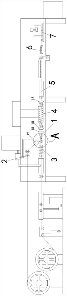
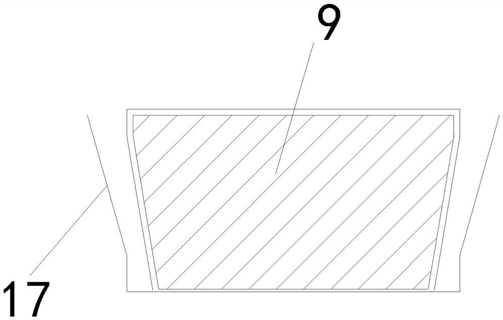
[0019] see Figure 1 to Figure 6 As shown, the spacer profile production line includes a squeeze roll 1 and a heat insulation strip transfer roll 2 and a metal sheet roll 3 arranged upstream of the squeeze roll 1. The downstream of the squeeze roll 1 is sequentially provided with a heating channel 4, a cooling channel 5, a straightening device 6 and The slitting device 7, the upstream of the squeezing roller 1 is also provided with a fixing frame 8 located on the heat insulation strip conveying roller 2 and the sheet metal roller 3, the fixing frame 8 is hingedly connected to the squeeze position passing through the squeezing roller 1 and then passes through in turn. A linear mandrel 9 is passed over the heating channel 4, the cooling channel 5 and the straightening device 6 and overlapped on the table of the slitting device 7, the end of the mandrel 9 is located upstream of the slitting position on the table.
[0020] The mandrel 9 includes an upstream section 10 located upstream of the cooling channel 5, an insulating section 11 fixed on the downstream end of the upstream section 10, and a downstream section 12 fixed downstream of the insulating section 11, both the upstream section 10 and the downstream section 12. Steel, copper or aluminum material is used, and the heat insulating section 11 is made of silica gel. The downstream end of the upstream section 10 is provided with a T-shaped upstream embedded portion 13 with a spherical cap-shaped end surface, and the upstream end of the downstream section 12 is provided with a T-shaped downstream embedded portion 14 with an end surface in the shape of a ball-drop groove. Preferably, the cross-sectional shape of the core mold 9 is an inverted trapezoid at the position of the lower pressing roller, and then a rectangle.
[0021] The outlet of the sheet metal roll 3 is flush with the inlet of the squeeze roll 1. Between the sheet metal roll 3 and the squeeze roll 1, there are an upper lift roll 15 and a lower pressure roll 16, and the metal sheet 17 comes out of the sheet metal roll 3 in sequence. It goes around the top of the upper lift roll 15 and the bottom of the lower pressure roll 16, and enters the squeeze roll 1. The top of the upper lift roll 15 is higher than the outlet of the sheet metal roll 3, and the bottom of the lower pressure roll 16 is lower than that of the squeeze roll 1. Entrance. Preferably, in order to ensure that the spacer profiles can be extruded into a rectangle, in addition to the upper and lower pairs of rollers, left and right pairs of rollers 18 are added to the extrusion roller 1, and left and right pairs of rollers are also added between the heating channel 4 and the cooling channel 5. 18, in order to ensure the bonding strength of the metal sheet and the two wings of the heat insulation strip.
[0022] A heat insulating strip gluing device 19 for gluing the outer sides of the two wings of the heat insulating strip is arranged between the heat insulating strip conveying roller 2 and the squeezing roller 1 .
[0023] The above only describes the preferred application examples of the present invention, but should not be construed as a limitation on the claims. The structure of the present invention may have other changes and is not limited to the above-mentioned structure. In a word, all changes made within the protection scope of the independent claims of the present invention are all within the protection scope of the invention.

PUM

no PUM

Description & Claims & Application Information

We can also present the details of the Description, Claims and Application information to help users get a comprehensive understanding of the technical details of the patent, such as background art, summary of invention, brief description of drawings, description of embodiments, and other original content. On the other hand, users can also determine the specific scope of protection of the technology through the list of claims; as well as understand the changes in the life cycle of the technology with the presentation of the patent timeline. Login to view more.

Similar technology patents

Hard alloy coating matrix added with rare earth

InactiveCN102644001APrevent rare earth oxidationHigh bonding strength
Owner:CHENGDU BANGPU CUTTING TOOLS CO LTD

Speaker and method of producing the same

InactiveCN101053278AHigh bonding strengthachieve flat
Owner:PANASONIC CORP

Surface plating technique for polymer material product

ActiveCN105316624AImprove flatness and finishHigh bonding strength
Owner:无锡纳弧新材料科技有限公司

Lead and carbon mixture and method for manufacturing lead-acid battery electrode plate

ActiveCN103078083AHigh bonding strengthFlexible process
Owner:湖北雄韬电源科技有限公司

Classification and recommendation of technical efficacy words

Why Eureka
Try Eureka