Novel dry-process cement kiln tail preheating system

A dry process cement, a new type of technology, is applied in the field of preheating at the end of the cement kiln, which can solve the problems of increasing the environmental burden and increasing the cost, and achieve the effect of increasing the daily output and saving the construction cost and time.

Active Publication Date: 2021-05-14
胡长庚
View PDF8 Cites 2 Cited by
  • Summary
  • Abstract
  • Description
  • Claims
  • Application Information

AI Technical Summary

Problems solved by technology

The current practice is to directly dismantle the kiln tail preheating tower with a daily output of new dry process cement clinker below 2,500 tons (inclusive), and build a new larger new dry process cement with a daily output of more than 4,000 tons (inclusive) of kiln tail preheating tower , the current practice not only significantly increases the cost, but also increases the environmental burden

Method used


Image

  • Novel dry-process cement kiln tail preheating system
  • Novel dry-process cement kiln tail preheating system
  • Novel dry-process cement kiln tail preheating system

Examples


Embodiment 1

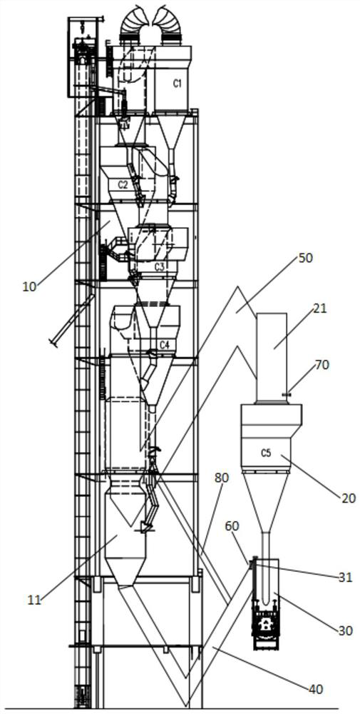
[0049] A new dry process cement kiln tail preheating system, such as figure 1 As shown, it includes a preheating tower 10, an external preheater 20 and a kiln tail smoke chamber 30. The preheating tower 10 is provided with a preheating system and a calciner 11. The preheating system includes a top-down The multi-stage preheater in the tower is 1 set (single series) including C1, C2, C3 and C4. The furnace 11 is connected, and an air inlet of the calciner 11 is connected with the kiln tail smoke chamber 30 through the first bent pipe 40, wherein the first bent pipe 40 is one bend, and the first bent pipe 40 is connected to the kiln tail smoke chamber 30. A burner 60 is provided at the junction of the kiln tail smoke chamber 30, and the air inlet pipe of the lowest stage preheater of the multi-stage tower internal preheater, that is, C4, passes through the second bent pipe 50 and the tower external preheater 20 The air outlet duct 21 is connected to each other, wherein the seco...

Embodiment 2

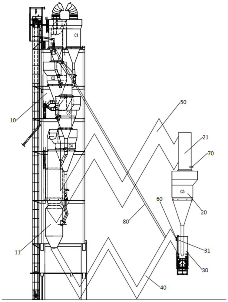
[0051] A new dry process cement kiln tail preheating system, such as figure 2 As shown, it includes an original preheating tower 10, an external preheater 20 and a kiln tail smoke chamber 30. The preheating tower 10 is provided with a preheating system and a calciner 11. The preheating system includes The multi-stage tower preheater set up from top to bottom is 1 set (single series) including C1, C2, C3 and C4, and the bottom preheater of the multi-stage tower preheater is the output of C4 The mouth is connected with the calciner 11, and an air inlet of the calciner 11 is connected with the kiln tail smoke chamber 30 through the first bent pipe 40, wherein the first bent pipe 40 is 4 bends, and the first bent pipe A burner 60 is provided at the joint between the road 40 and the kiln tail smoke chamber 30, and the air inlet pipe of the lowest stage preheater of the multi-stage tower inner preheater, that is, the air inlet pipe of C4, is connected with the tower external prehea...

Embodiment 3

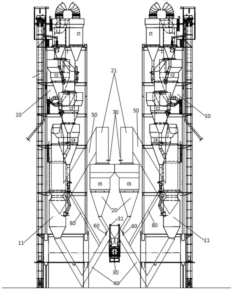
[0053] A new dry process cement kiln tail preheating system, such as image 3 As shown, it includes 2 preheating towers 10, 2 tower external preheaters 20 and 1 kiln tail smoke chamber 30. Each preheating tower 10 is provided with a preheating system and a calciner 11. The preheating system includes The multi-stage tower preheater set up from top to bottom is 1 set (single series) including C1, C2, C3 and C4, and the bottom preheater of the multi-stage tower preheater is the output of C4 The inlet is connected with the calciner 11, and one air inlet of the calciner 11 is connected with the kiln tail smoke chamber 30 through the first bending pipe 40, and the calciner 11 in the other preheating tower 10 is also connected through another first bending pipe. The pipe 40 is connected to the kiln tail smoke chamber 30, wherein the first bent pipe 40 is one bend, and a burner 60 is provided at the junction of the first bent pipe 40 and the kiln tail smoke chamber 30, and the multi-s...


PUM


Abstract

A novel dry-process cement kiln tail preheating system comprises a preheating tower, an out-tower preheater and a kiln tail smoke chamber, at least one set of preheating system and a decomposing furnace are arranged in the preheating tower, each set of preheating system comprises multiple stages of in-tower preheaters arranged from top to bottom, a discharging port of a lowest-stage preheater of the multiple stages of in-tower preheaters is connected with the decomposing furnace, the kiln tail smoke chamber is connected with an air inlet of the decomposing furnace through a first bent pipeline, and an air inlet pipeline of the downmost-stage preheater of the multiple stages of in-tower preheaters is connected with an air outlet pipeline of the out-tower preheater through a second bent pipeline. According to the invention, a downmost-stage preheater in an existing novel dry-process cement kiln tail preheating tower with daily clinker yield of 2500 tons or less is moved out of the preheating tower, meanwhile, the kiln tail smoke chamber in the preheating tower is detached, and a larger kiln tail smoke chamber is arranged outside the preheating tower, so that after the transformation, the daily output of the cement clinker is improved, the coal consumption is reduced, the power consumption is reduced, the emission of harmful gas nitric oxide is reduced, and the transformation cost is greatly reduced.

Description

technical field [0001] The invention belongs to the technical field of cement kiln tail preheating, and in particular relates to a novel dry-process cement kiln tail preheating system. Background technique [0002] The kiln tail preheating tower of the existing new dry-process cement with a daily output of 2,500 tons or less of clinker is usually composed of a calciner and a five-stage preheater. The preheaters are numbered C1, C2, C3, and C4 from top to bottom. , C5, C1 are 2 or 1, and C2, C3, C4, C5 are 1. The raw meal is transported to the preheater through the conveying equipment, and the preheated raw meal enters the calciner, and the fuel is added in the calciner. The raw meal is decomposed inside, and the decomposed raw meal enters the C5 through its feeding pipe through the kiln tail smoke chamber and enters the rotary kiln for calcination to become clinker. The kiln tail smoke chamber is set in the preheating tower. [0003] The kiln tail preheating tower with a da...

Claims


Application Information

Patent Timeline
Patent Type & Authority Applications(China)
IPC IPC(8): C04B7/43C04B7/38
CPCC04B7/432C04B7/38
Inventor 胡长庚
Owner 胡长庚
Why Eureka
Try Eureka