Track ballast inspection system based on binocular vision and working method thereof

A binocular vision and inspection system technology, applied in image data processing, instruments, calculations, etc., can solve the problems of inaccurate and objective detection results, inconsistent detection standards, time-consuming and cost-consuming, etc., to achieve convenient portability and improve search efficiency , The effect of reducing the cost of equipment

Pending Publication Date: 2021-05-14
中科(湖南)先进轨道交通研究院有限公司
View PDF0 Cites 1 Cited by
  • Summary
  • Abstract
  • Description
  • Claims
  • Application Information

AI Technical Summary

Problems solved by technology

[0004] In view of the above defects or improvement needs of the prior art, the present invention provides a binocular vision-based track ballast inspection system and its working method, the purpose of which is to solve the large detection error existing in the existing ballast manual inspection problems, as well as the technical problems of manpower fatigue and visual fatigue due to the heavy workload of ballast inspection, which are quite time-consuming and costly, and the technical problems of inaccurate and objective test results due to the inconsistency of testing standards

Method used


Image

  • Track ballast inspection system based on binocular vision and working method thereof
  • Track ballast inspection system based on binocular vision and working method thereof
  • Track ballast inspection system based on binocular vision and working method thereof

Examples


Embodiment Construction

[0063] In order to make the object, technical solution and advantages of the present invention clearer, the present invention will be further described in detail below in conjunction with the accompanying drawings and embodiments. It should be understood that the specific embodiments described here are only used to explain the present invention, not to limit the present invention. In addition, the technical features involved in the various embodiments of the present invention described below can be combined with each other as long as they do not constitute a conflict with each other.

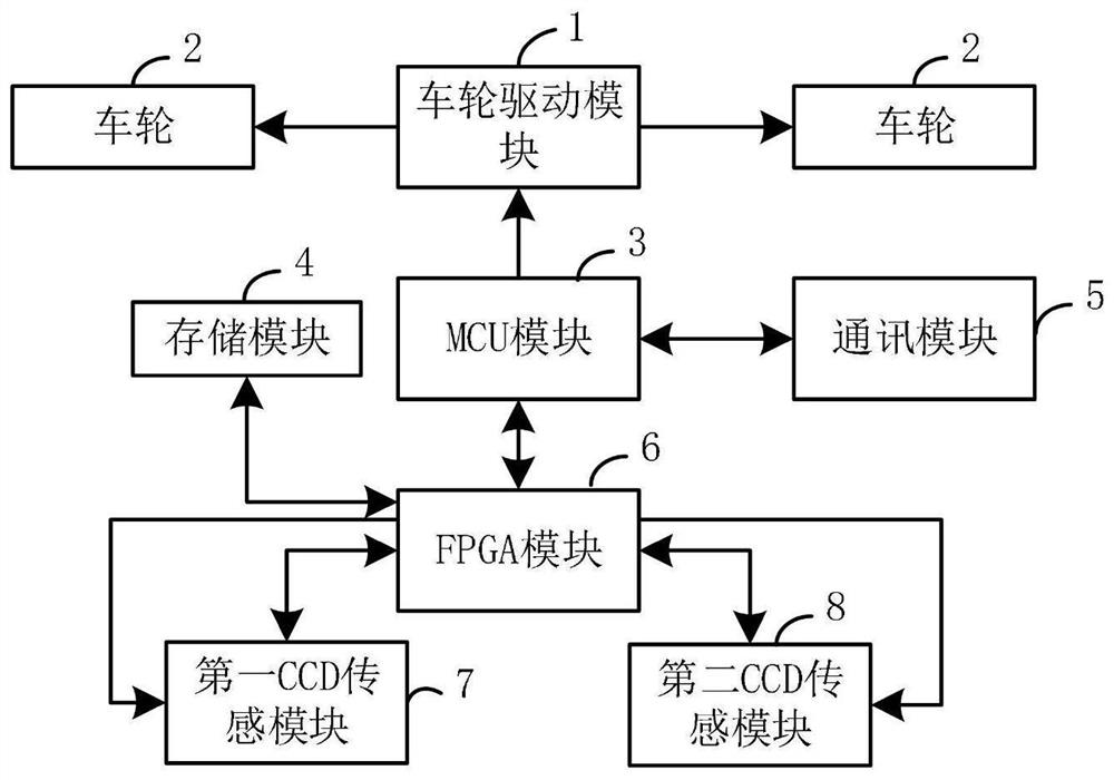
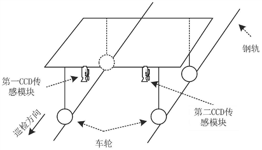
[0064] Such as figure 1 and image 3 As shown, according to the first aspect of the present invention, a kind of track ballast inspection system based on binocular vision is provided, and it is arranged on the rail (refer to simultaneously image 3 shown), and includes a wheel drive module 1, a plurality of wheels 2, an MCU module 3, a storage module 4, a communication module 5, an FPGA module...


PUM


Abstract

The invention discloses a track ballast inspection system based on binocular vision, which is arranged on a rail and comprises a wheel driving module, a plurality of wheels, an MCU module, a storage module, a communication module, an FPGA module, a first CCD sensing module, a second CCD sensing module and a man-machine interaction module. The wheel driving module is electrically connected with a plurality of wheels and the MCU module, the MCU module is electrically connected with the communication module and the FPGA module, the FPGA module is electrically connected with the storage module, the first CCD sensing module, the second CCD sensing module and the man-machine interaction module, and the optical axis of the first CCD sensing module and the optical axis of the second CCD sensing module are perpendicular to a rail. The invention can solves the the technical problems of large detection error in the existing railway ballast manual detection, the technical problems of manpower fatigue, visual fatigue and considerable time cost caused by large workload of railway ballast detection, and the technical problems of manpower fatigue, visual fatigue and considerable time cost consumption caused by large workload of railway ballast inspection.

Description

technical field [0001] The invention belongs to the technical field of railway operation safety, and more specifically relates to a binocular vision-based track ballast inspection system and a working method thereof. Background technique [0002] In the process of railway maintenance, some cables and sensors are often installed. In order to avoid man-made damage and affect the appearance of the railway, these sensors and cables are generally buried in a deep position under the ballast and backfilled after installation After a long period of time, due to trampling and excavation and backfilling of the ballast by people coming and going, a lot of ballast stones will be lost, and the height of the ballast will be lower and lower. [0003] At present, the railway system usually uses manual inspection for ballast inspection. However, there are many shortcomings in the manual inspection method: first, because manual inspection can only judge the height of ballast by visual inspect...

Claims


Application Information

Patent Timeline
Patent Type & Authority Applications(China)
IPC IPC(8): G06T7/00G06T7/13G06T5/50G06T5/00G06T7/55
CPCG06T5/007G06T5/50G06T7/0002G06T2207/10028G06T2207/20216G06T2207/20228G06T7/13G06T7/55
Inventor 李思丰刘洋
Owner 中科(湖南)先进轨道交通研究院有限公司
Why Eureka
Try Eureka