Common-mode voltage elimination method based on parallel driver topological structure

A topology and common-mode voltage technology, applied in electrical components, output power conversion devices, AC power input to DC power output, etc., can solve the problem of small switching loss, achieve the elimination of common-mode voltage and reduce damage Effect

Active Publication Date: 2021-05-14
XIAN TECH UNIV
View PDF6 Cites 0 Cited by
  • Summary
  • Abstract
  • Description
  • Claims
  • Application Information

AI Technical Summary

Problems solved by technology

[0007] In order to solve the problem of eliminating common-mode voltage, the present invention provides a method for eliminating common-mode voltage based on parallel driver topology with low switching loss, good isolation effect and high efficiency

Method used


Image

  • Common-mode voltage elimination method based on parallel driver topological structure
  • Common-mode voltage elimination method based on parallel driver topological structure
  • Common-mode voltage elimination method based on parallel driver topological structure

Examples


Embodiment 1

[0027] There is a lot of research on common-mode voltage cancellation, but it is only 20 years old, so the technology is not perfect, and there is still a lot to continue to research and learn. Based on the prior art, the present invention proposes innovative assumptions and modulation techniques, further improves the original method for eliminating common-mode voltage, reduces switching loss, and eliminates common-mode voltage.

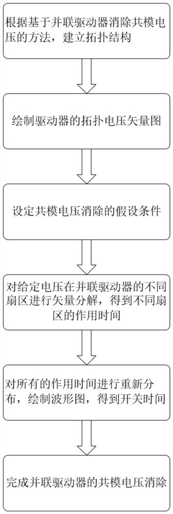
[0028] The present invention is a common-mode voltage elimination method based on parallel driver topology, see figure 1 , including the following steps:

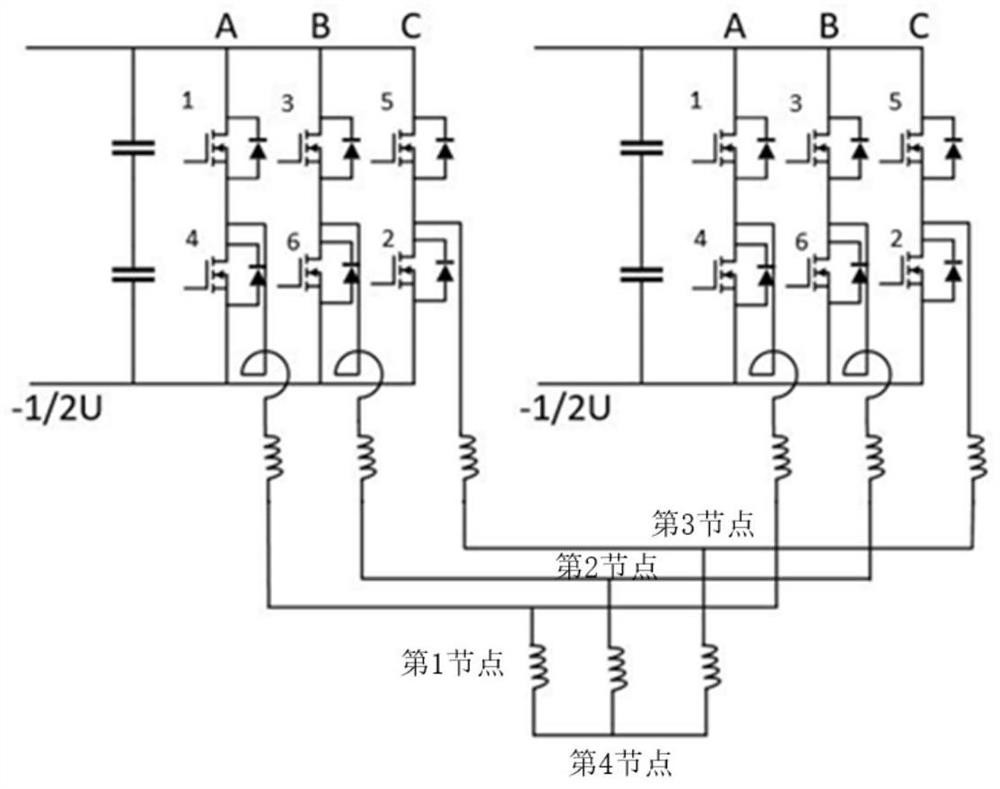
[0029] Step 1: establish topological structure: the topological structure of the present invention originates from two drivers that are formed in parallel, see figure 2 , figure 2is the circuit structure diagram of the parallel driver, figure 2 The voltages generated by the two drivers are equal in magnitude and opposite in direction. Each driver is sequentially connected with three bridge ...

Embodiment 2

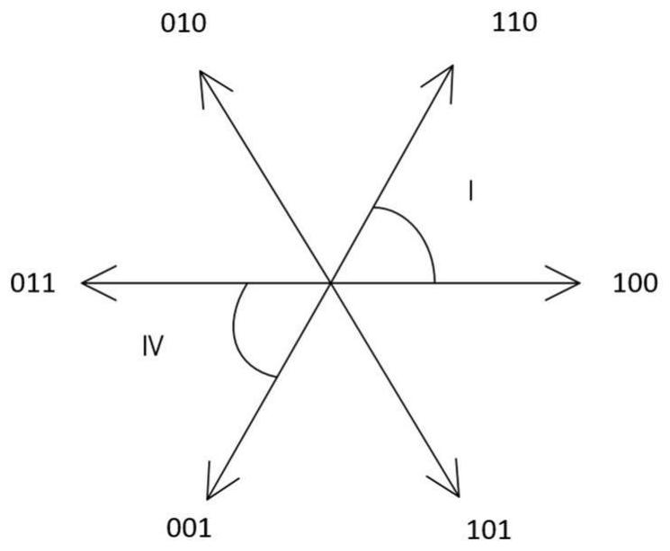
[0041] The common-mode voltage elimination method based on the parallel driver topology is the same as that in Embodiment 1. The vector decomposition of the given voltage in different sectors of the parallel driver described in step 4 of the present invention is to substitute the assumed conditions into the voltage vector decomposition expression decomposition calculation. , to obtain the action time of a given voltage in different sectors, taking the voltage of the first sector as an example, including the following steps:

[0042] (4.1) Decompose the given voltage vector to obtain the decomposition expression: the first sector voltage vector

[0043] The solution expression is:

[0044]

[0045] x 1 +x 3 = 0.5;

[0046] x 2 +x 4 =0.5

[0047] in: For a given voltage, x 1 、x 2 、x 3 、x 4 For the four action times of the given voltage after the decomposition of the first sector, is the voltage vector decomposed by a given voltage in the first sector and the two...

Embodiment 3

[0061] The common-mode voltage elimination method based on the topology of parallel drivers is the same as in embodiment 1-2, redistribute all the action time described in step 5, draw the waveform diagram, and obtain the switching time, which is the given voltage vector obtained in step 4 The decomposed action time is combined with the carrier to obtain the switching time based on the parallel driver topology, and the linear relationship between the given voltage vector and action time obtained in step 4 is substituted into the switching time to obtain the mathematical expression of the given voltage vector and switching time The formula is an innovative modulation technique proposed by the present invention. Taking the first sector as an example, it includes the following steps:

[0062] (5.1) The action time x after decomposing the given voltage vector calculated in step 4 1 、x 2 、x 3 、x 4 Combining with the carrier, draw the ladder diagram, and get the switching time a ...


PUM


Abstract

The invention discloses a common-mode voltage elimination method based on a parallel driver topological structure. The common-mode voltage elimination method solves the problem of effectively eliminating common-mode voltage under high and low frequencies. The method comprises the following steps of: establishing a topological structure for eliminating common-mode voltage according to a parallel driver; drawing a topological voltage vector diagram; putting forward assumed conditions of common-mode voltage elimination; performing vector decomposition on different sectors of the given voltage to obtain action time of different sectors; redistributing all action time, drawing an oscillogram, and modulating to obtain switching time; and completing common-mode voltage elimination of the parallel drivers. According to the method, assumed conditions are proposed to generate voltages which are equal in size and opposite in direction in a parallel driver topological structure, and given voltages are subjected to vector decomposition in each sector; and the obtained action time is redistributed and modulated, and the common-mode voltage is eliminated. The topological structure is simple, easy to construct and convenient to understand; and the common-mode voltage can be effectively eliminated without a specific environment. The method is used in the fields of automotive electronics, medical instruments and aerospace.

Description

technical field [0001] The invention belongs to the technical field of power electronics, and mainly relates to common-mode voltage elimination. Specifically, it is a common-mode voltage elimination method based on parallel driver topology. The invention does not require a specific environment and can completely eliminate common-mode voltage. There are a wide range of applications in the fields of equipment and aerospace. Background technique [0002] The brushless DC motor has the characteristics of simple structure and large output torque. Theoretically, the model for eliminating the common-mode voltage is two drivers connected in parallel, each driver has three bridge arms, and each bridge arm is composed of diodes and transistors. The voltages generated by the two drivers are equal in magnitude and opposite in direction, and the common-mode voltage can be eliminated. [0003] The common mode voltage will induce a high-amplitude shaft voltage on the motor shaft, forming...

Claims


Application Information

Patent Timeline
Patent Type & Authority Applications(China)
IPC IPC(8): H02M7/5387H02M1/12H02M1/088
CPCH02M7/53871H02M1/12H02M1/088
Inventor 谭博代佳伟陈超波倪志浩
Owner XIAN TECH UNIV
Why Eureka
Try Eureka