Cutting method for fabricated building steel structure machining

A construction steel and assembly technology, which is applied in the direction of metal processing, metal processing equipment, metal processing machinery parts, etc., can solve the problems of inconvenient operation and no way to ensure complete cutting

Pending Publication Date: 2021-05-18
青岛北洋建筑设计有限公司
View PDF0 Cites 3 Cited by
  • Summary
  • Abstract
  • Description
  • Claims
  • Application Information

AI Technical Summary

Problems solved by technology

[0007] When steel pipes are in use, they need to be cut to a certain length according to actual construction or assembly requirements, and in prefabricated buildings, a certain amount of steel pipes need to be processed in batches for assembly needs; the existing steel pipe cutting equipment, through Fix the steel pipe on the workbench, and cut the steel pipe through the moving cutting

Method used


Image

  • Cutting method for fabricated building steel structure machining
  • Cutting method for fabricated building steel structure machining
  • Cutting method for fabricated building steel structure machining

Examples


Embodiment 1

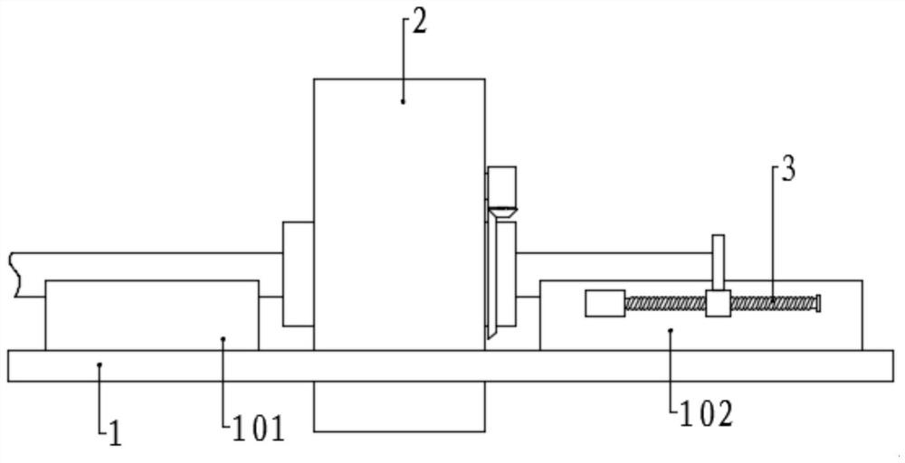
[0051] Please refer to the accompanying drawings, the present invention provides a technical solution: a kind of cutting equipment for the processing of prefabricated building steel structures, including a workbench 1, a cutting box 2 is fixed on the workbench 1, two corresponding cutting box 2 on the workbench 1 The side positions are respectively provided with a first support platform 101 and a second support platform 102, and one side of the second support platform 102 is provided with a limit assembly 3, and the top surfaces of the first support platform 101 and the second support platform 102 are provided with groove, and the bottom surface of the placement groove is set as a V-shaped surface;

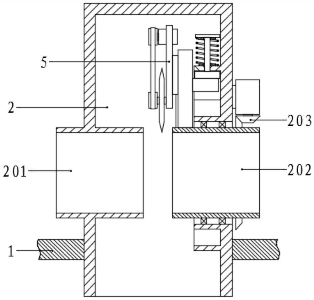
[0052] The left side wall of the cutting box 2 is fixed with a fixed cylinder 201, the right side wall is fixed with a rotating cylinder 202, and the outer section of the rotating cylinder 202 is fixed with a bevel gear ring, the bevel gear gear is engaged with a first bevel gear 2...

Embodiment 2

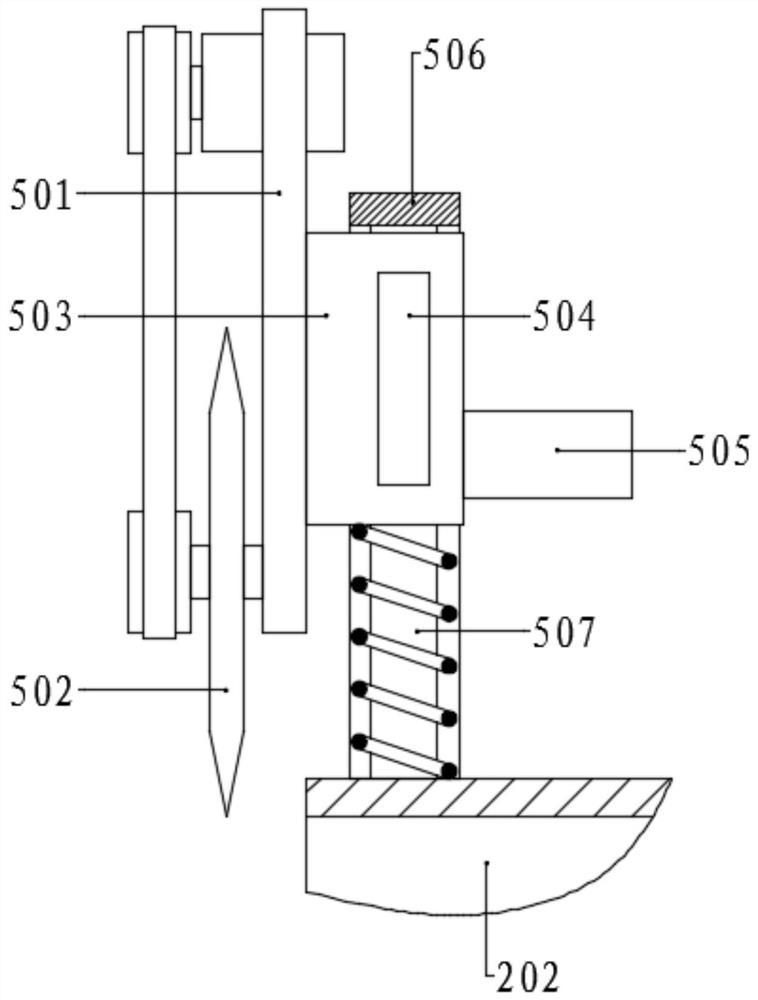
[0061] The structure of this embodiment is basically the same as that of Embodiment 1, the difference is that the cutting assembly 5 includes a turret 506 fixed on the inner section of the rotating cylinder 202, a moving block 503 is slidably connected to the turret 506, and the moving block 503 and A spring is arranged between the side walls of the rotating cylinder 202, and a sliding block 504 is symmetrically fixed on both sides of the moving block 503, and a chute 507 is correspondingly provided on the inner side wall of the turret 506, and the sliding block 504 is slidably connected to the chute 507 Among them, the side of the moving block 503 close to the circular slide rail 204 is fixed with a sliding shaft 505, the sliding shaft 505 is slidably connected in the circular sliding rail 204, and the other side of the moving block 503 is fixed with a moving plate 501, and the moving plate 501 The outer surface is rotatably connected with a cutting knife 502, and the outside ...

Embodiment 3

[0071] The structure of the present embodiment is basically the same as that of the second embodiment, the difference being that the outer section of the second support platform 102 is provided with a trough 104, the bottom surface of the trough 104 is inclined, and the inclination angle is the same as that of the V-shaped surface of the placement trough. Wherein one side is identical, and the bottom surface top of unloading chute 104 coincides with the corresponding side of V-shaped surface, the position of corresponding unloading chute 104 on the workbench 1 is provided with notch, and the below of notch is provided with conveyer belt 401, conveyer belt Both sides of 401 are provided with conveying wheels 4 symmetrically, one of which is connected with a motor, and the conveying wheels 4 are connected to the ground through a bracket 107 .

[0072] The two inclined surfaces of the V-shaped surface are respectively arranged uniformly along the length direction and are connected...


PUM


Abstract

The invention discloses a cutting method for fabricated building steel structure machining, and belongs to the technical field of building structures. A workbench, a cutting box, a first supporting table and a second supporting table are included, a limiting assembly is arranged on one side of the second supporting table, the cutting box is provided with a fixed cylinder and a rotating cylinder, and the rotating cylinder is provided with a cutting assembly. A circular sliding rail and a pushing groove are fixed to the corresponding side wall of the cutting box, and a pushing assembly is arranged in a pushing groove. According to the cutting method for fabricated building steel structure machining, the position of a limiting plate is adjusted, so that the cutting length of a steel pipe is determined through the distance between the limiting plate and a cutting knife; and the to-be-cut steel pipe is placed on the first supporting table, the steel pipe is moved, the end of the steel pipe makes contact with the limiting plate on the second supporting table, a cutting assembly is started, the cutting knife conducts cutting around the steel pipe by one circle, after cutting is finished, the limiting effect of a limiting assembly is cancelled, the to-be-machined steel pipe is pushed, the cut steel pipe is forced to move outwards, and the cut steel pipe is discharged.

Description

technical field [0001] The invention relates to the technical field of building structures, in particular to a cutting method for processing assembled building steel structures. Background technique [0002] Prefabricated buildings are buildings assembled from prefabricated components on site, called prefabricated buildings. According to the form and construction method of prefabricated components, it is divided into five types: block building, plate building, box building, skeleton plate building and rising plate building. [0003] Block building is a prefabricated block building with prefabricated block materials to build walls. It is suitable for building 3-5 storey buildings. If the strength of blocks is improved or steel bars are configured, the number of floors can also be appropriately increased. Block building has strong adaptability, simple production process, convenient construction, low cost, and local materials and industrial waste can also be used. Building bl...

Claims


Application Information

Patent Timeline
IPC IPC(8): B23D21/04B23Q3/00B23Q3/18B23Q7/05B23Q7/00
CPCB23D21/04B23Q3/00B23Q3/18B23Q7/003B23Q7/05
Inventor 夏世群杜涛
Owner 青岛北洋建筑设计有限公司
Why Eureka
Try Eureka