
Piston welding device and method

A welding device and welding method technology, applied in the direction of piston, welding equipment, electron beam welding equipment, etc., can solve the problems of increasing the total welding time, unsatisfactory effect, waiting for a period of time before welding another seam, etc.

Active Publication Date: 2021-05-18
湖南江滨机器(集团)有限责任公司
View PDF7 Cites 1 Cited by
  • Summary
  • Abstract
  • Description
  • Claims
  • Application Information

AI Technical Summary

Problems solved by technology

[0004] Among them, method 1 requires two preheating, two heat preservation, two clamping pistons, and two vacuum pumping during welding, which requires a lot of repetitive work time and is not efficient; and repeated preheating and heat preservation will affect the substrate Performance
Method 2 The piston is clamped once, although the efficiency has been improved, but in order to avoid the local temperature of the piston from being too high, usually after welding one seam, it is necessary to wait for a period of time before welding another seam, which increases the total welding time and reduces production efficiency
In addition, the above two solutions can only weld a weld in a fixed direction. The direction and position of the welding torch cannot be adjusted freely. Generally, the ring seam can only be welded in the horizontal direction, and the top seam can only be welded in the vertical direction. The degree of flexibility is low. Unsatisfactory effect

Method used


Image

  • Piston welding device and method
  • Piston welding device and method
  • Piston welding device and method

Examples


Embodiment Construction

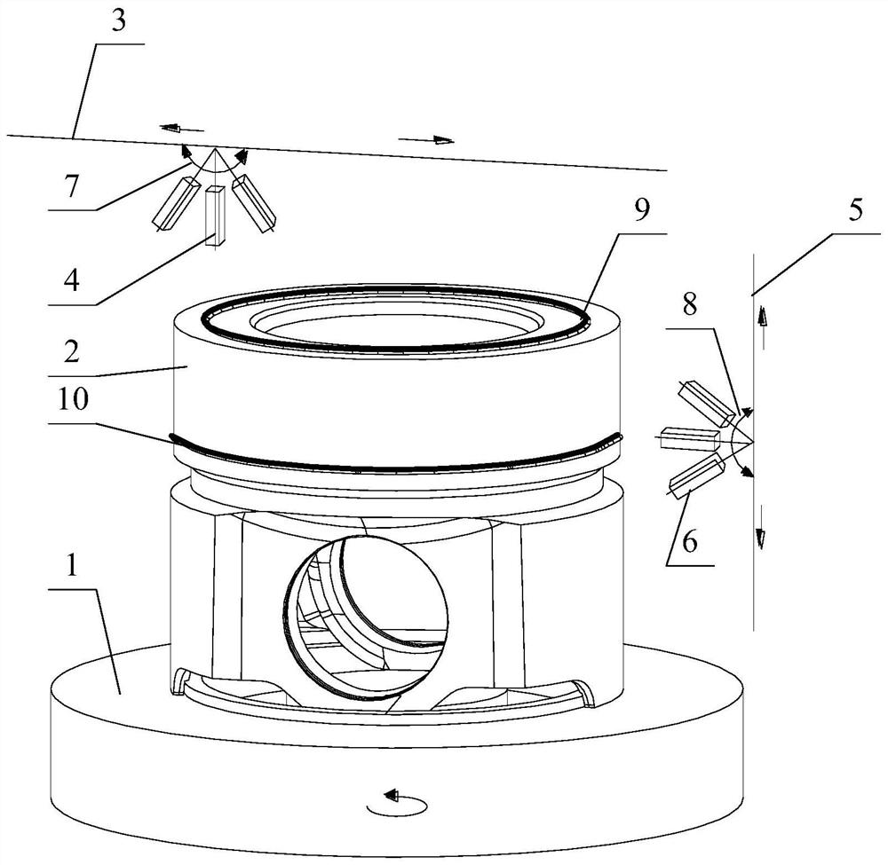
[0038] The core of this specific embodiment is to provide a piston welding device, which can simplify the process of piston welding, improve work efficiency, and solve the current problems in this field.

[0039] Hereinafter, an embodiment will be described with reference to the drawings. In addition, the examples shown below do not limit the content of the invention described in the claims in any way. In addition, all the contents of the configurations shown in the following embodiments are not limited to be essential to the solutions of the invention described in the claims.

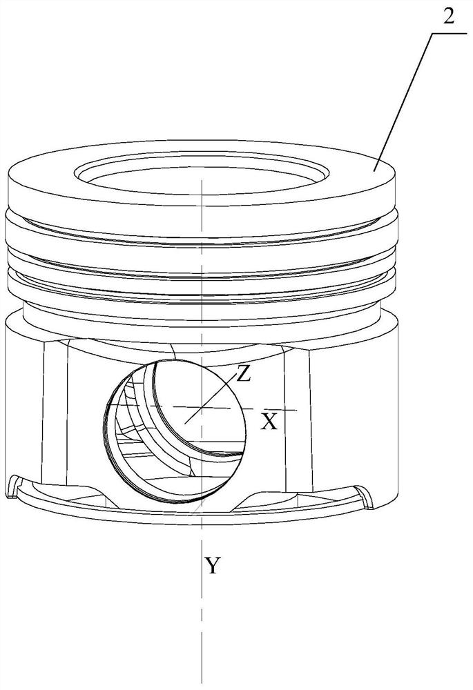
[0040] The piston welding device provided in this specific embodiment includes: a worktable 1, a first linear guide rail 3, and a second linear guide rail 5; The piston 2 rotates around the central axis of the piston 2; the first linear guide 3 is located above the piston 2 and parallel to the long axis of the piston 2, and the first linear guide 3 is provided with a first welding torch 4 for welding ...


PUM


Abstract

The invention discloses a piston welding device and method. The device comprises a workbench, a first linear guide rail and a second linear guide rail. The workbench is provided with a fixing part matched with a lower end spigot of a piston and can drive the piston to rotate around the central axis of the piston. The first linear guide rail is located above the piston and is parallel to the long axis of the piston, a first welding gun used for welding a top seam is arranged on the first linear guide rail, and the first welding gun can move along the first linear guide rail. The second linear guide rail is parallel to the central axis and is located on the side face of the piston. The second linear guide rail is provided with a second welding gun used for welding a circular seam, and the second welding gun can move along the second linear guide rail. During actual use, the positions of the first welding gun and the second welding gun on the first linear guide rail and the second linear guide rail are adjusted respectively, then the top seam and the circular seam can be welded by rotating the workbench, and the working efficiency is improved.

Description

technical field [0001] The invention relates to the technical field of piston welding, and more specifically, to a piston welding device and method. Background technique [0002] At present, the explosion pressure of domestically developed diesel engines for vehicles has exceeded 20MPa, making it difficult for traditional cast aluminum pistons to meet the reliability requirements of high-performance diesel engines. Therefore, all-steel pistons have been popularized in China. It is forged and connected by welding to form a closed cooling oil chamber. [0003] As far as the existing technology is concerned, piston welding methods include: laser welding, friction welding, and electron beam welding; among them, electron beam is widely used because of its advantages such as large aspect ratio, vacuum welding, high welding strength, and less pore defects. There are two commonly used electron beam welding piston methods, method one: preheating before welding → circular seam (top s...

Claims


Application Information

Patent Timeline
Patent Type & Authority Applications(China)
IPC IPC(8): B23K15/00
CPCB23K15/0053B23K2101/003
Inventor 王奕澍杨志勇胡厅谭爱明戴凌云谭小东梅策源
Owner 湖南江滨机器(集团)有限责任公司
Learn More