
Gradient printing equipment and printing process thereof

A technology of printing equipment and mixing box, used in printing, printing presses, rotary printing presses, etc., can solve the problems of uneven mixing of dyes, affecting the printing quality of display screens, and adjusting the speed of dye discharge.

Pending Publication Date: 2021-05-18
深圳市旺博科技有限公司
View PDF13 Cites 0 Cited by
  • Summary
  • Abstract
  • Description
  • Claims
  • Application Information

AI Technical Summary

Problems solved by technology

[0003] In the prior art, when the gradient printing equipment is processing the display screen, the dye mixing is not uniform enough, which affects the printing quality of the display screen. At the same time, the device is not convenient to adjust the discharge speed of the dye according to the printing requirements.

Method used


Image

  • Gradient printing equipment and printing process thereof
  • Gradient printing equipment and printing process thereof
  • Gradient printing equipment and printing process thereof

Examples


Embodiment

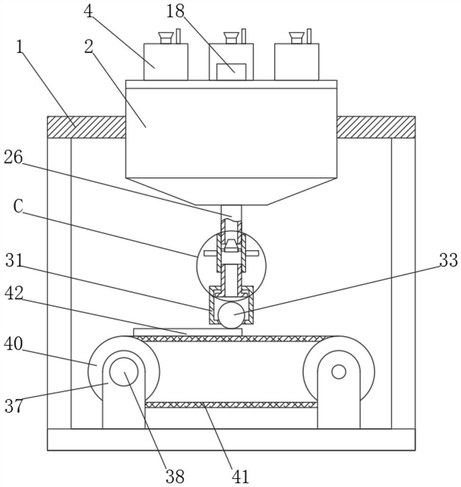
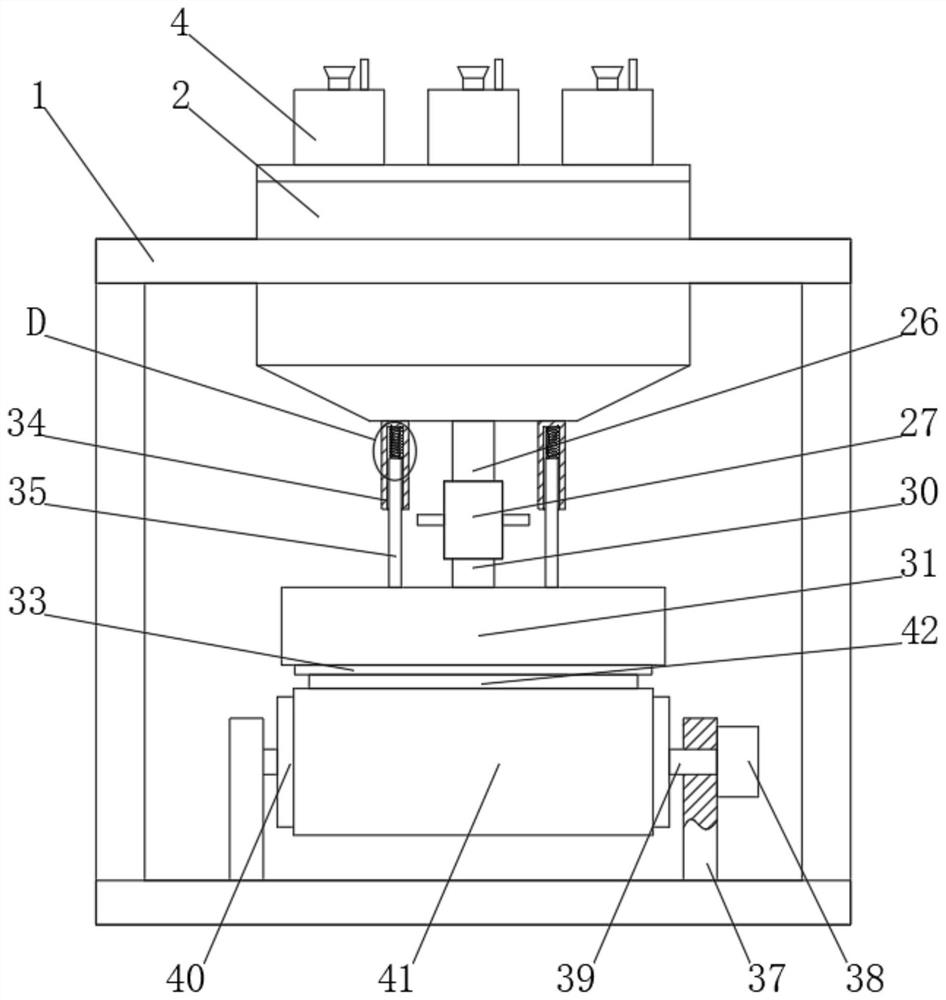
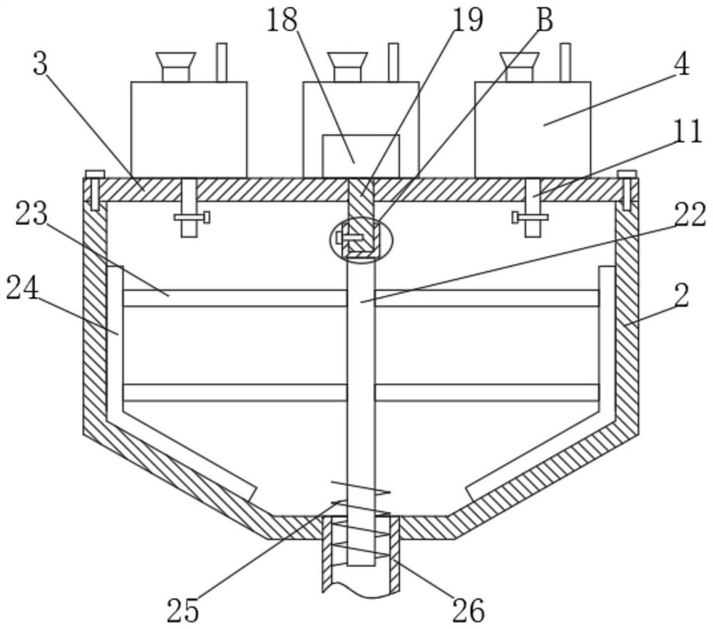
[0034] A gradient printing device, comprising a frame body 1, the upper end of the frame body 1 is fixedly sleeved with a mixing box 2, the upper end of the mixing box 2 is connected with a box cover 3 through screws, and the upper end of the box cover 3 is fixedly installed There are a plurality of barrels 4, a motor 18 is fixedly installed on the upper end of the box cover 3, a rotating shaft 19 is arranged on the lower end of the motor 18, a support 37 is welded on the inner side of the lower end of the frame body 1, and the support 37 A motor 38 is fixedly installed on the top, and the motor 38 is provided with a drive shaft 39. The drive shaft 39 is rotatably connected to the support 37, and the end of the drive shaft 39 away from the motor 38 is welded with a support roller 40. The support The outer side of the roller 40 is sleeved with a conveyor belt 41 , a material plate 42 is connected to the conveyor belt 41 , and a sealing roller 33 is connected to the upper end of ...


PUM


Abstract

The invention discloses gradient printing equipment. The gradient printing equipment comprises a frame body, wherein the upper end of the frame body is fixedly sleeved with a mixing box, the upper end of the mixing box is connected with a box cover through screws, a plurality of charging barrels are fixedly installed at the upper end of the box cover, a motor is fixedly installed at the upper end of the box cover, a rotating shaft is arranged at the lower end of the motor, a support is welded to the inner side of the lower end of the frame body, a motor is fixedly installed on the support, a driving shaft is arranged on the motor, the driving shaft is rotationally connected into the support, a supporting roller is welded to the end, away from the motor, of the driving shaft, the supporting roller is sleeved with a conveying belt, the conveying belt is in contact connection with a material plate, and the upper end of the material plate is in contact connection with a sealing roller. The invention relates to gradient printing equipment and a printing process thereof. The characteristics that dye mixing is more uniform, and the dye discharging speed is convenient to adjust are realized.

Description

technical field [0001] The invention belongs to the technical field of display screen processing, in particular to a gradient printing device and a printing process thereof. Background technique [0002] Thin-film transistor-liquid crystal display, an optoelectronic product that integrates large-scale semiconductor integrated circuits and flat-panel light source technology with thin-film transistors as control elements and liquid crystals as the medium, has become a new generation of mainstream displays. The display quality and overall performance of thin film transistor liquid crystal displays are largely affected by materials, device structures and processes. At present, the thin film transistor liquid crystal display is formed by injecting liquid crystal material between the array substrate and the color filter substrate after the array substrate and the color filter substrate are boxed together. During the processing of the display screen, the display screen is printed....

Claims


Application Information

Patent Timeline
Patent Type & Authority Applications(China)
IPC IPC(8): B41F17/00B41F31/02B41F31/03B41M1/14B41M1/26
CPCB41F17/00B41F31/03B41F31/02B41M1/14B41M1/26B41P2217/50B41P2217/60B41P2231/00B41P2233/30
Inventor 黄卫坚乾小锁
Owner 深圳市旺博科技有限公司
Learn More