Air-assisted jet flow flame ignition device and ignition method thereof

A flame ignition and air-assisted technology, applied in the direction of machines/engines, internal combustion piston engines, mechanical equipment, etc., can solve the problems of slow flame propagation speed and unstable combustion in the cylinder

Active Publication Date: 2021-05-18
TIANJIN UNIV
View PDF6 Cites 4 Cited by
  • Summary
  • Abstract
  • Description
  • Claims
  • Application Information

AI Technical Summary

Problems solved by technology

[0004] However, there are still some problems in the application of EGR technology. For example, if the EGR ra

Method used


Image

  • Air-assisted jet flow flame ignition device and ignition method thereof
  • Air-assisted jet flow flame ignition device and ignition method thereof
  • Air-assisted jet flow flame ignition device and ignition method thereof

Examples


Embodiment Construction

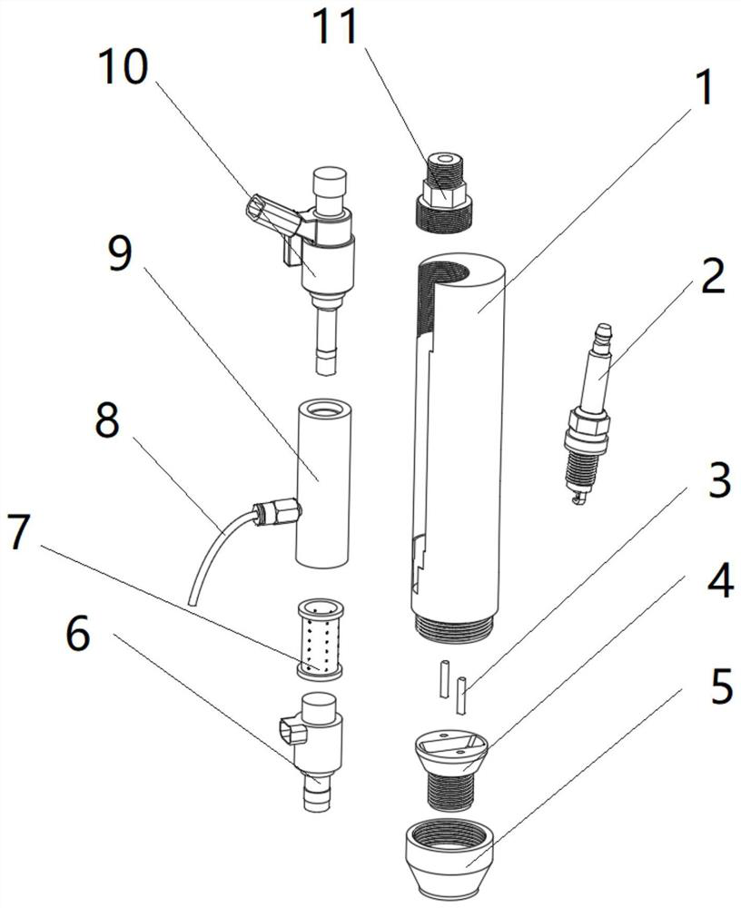
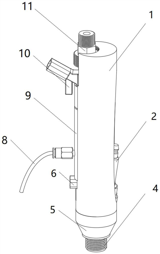
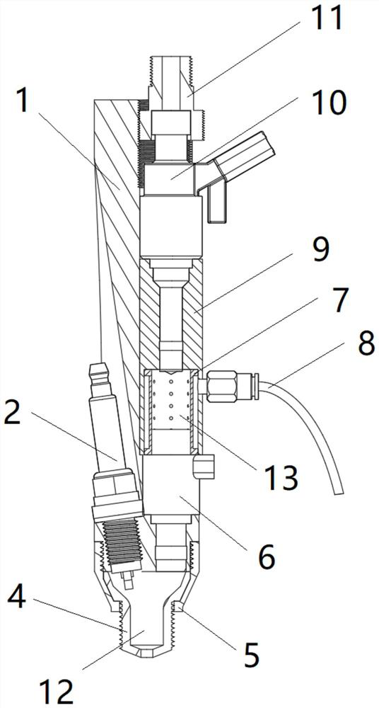
[0024] figure 1 It is an exploded view of the parts of the device of the present invention, which contains 10 parts in total, and is divided into three parts according to the functions: the housing, the fuel-air premixing unit and the pre-combustion chamber. Wherein the function of the housing 1 is to provide installation positions for other parts. The function of the fuel-air premixing unit is to provide pre-mixed air for the pre-combustion chamber. Including fuel injector 10, air injection valve 6, premixing sleeve inner core 7, premixing sleeve 9 and injector fastening bolt 11. The function of the pre-chamber is to provide the flame jet to the main combustion chamber. Contains spark plug 2, pre-chamber nozzle 4, positioning pin 3 and nozzle pressing piece 5.

[0025] During the installation process, the injection valve 6, the inner core 7 of the premixing sleeve, the premixing sleeve 9 and the fuel injector 10 are placed in sequence, and these four parts are pressed toge...


PUM


Abstract

The invention provides an air-assisted jet flow flame ignition device which comprises a shell (1), a fuel oil-air premixing unit and a pre-combustion chamber. The device is characterized in that the fuel oil-air premixing unit comprises an oil injector (10), an air injection valve (6), a premixing sleeve (9), a premixing sleeve inner core (7) and an oil injector fastening bolt (11), and the premixing sleeve inner core (7) arranged in the premixing sleeve (9), and an oil injector fastening bolt, wherein the inner wall surface of the premixing sleeve (9) and the outer wall surface of the premixing sleeve inner core (7) form a premixing sleeve inner cavity (14), the inner wall surface of the premixing sleeve inner core (7), the lower end surface of a nozzle of the oil injector (10) and the upper end surface of an air inlet of the air injection valve (6) form a premixing cavity (13), the premixing cavity (13) communicates with the premixing sleeve inner cavity (14) through a through hole in the sidewall of the premixing sleeve inner core (7), and a pre-combustion chamber nozzle (4) is fixedly connected to the lower part of the shell (1) through a positioning pin.

Description

technical field [0001] The invention belongs to the field of internal combustion engine combustion, in particular to an air-assisted jet flame ignition device suitable for high EGR rate engines. Background technique [0002] People's increasing attention to environmental and energy issues, as well as the increasingly stringent laws and regulations, are driving the development of internal combustion engines towards higher efficiency and lower emissions. EGR technology was first used as an effective means for diesel engines to reduce nitrogen oxides, and now it has been widely used in various vehicle engines. EGR technology can effectively reduce the temperature of the mixed gas in the cylinder by introducing exhaust gas into the intake port to dilute the mixed gas in the cylinder, thereby reducing the emission of nitrogen oxides. Experimental results show that nitrogen oxide emissions can be reduced by 50-70% with an EGR rate of 10%. At the same time, the application of EGR...

Claims


Application Information

Patent Timeline
IPC IPC(8): F02B19/10F02B19/12
CPCF02B19/1071Y02T10/12F02B19/10F02B19/12F02P13/00F02P5/1502F02P5/045F02D37/02F02D41/40F02M57/06F02B19/108F02B19/1028F02B19/1042F02P21/00F02B19/08F02B19/1023
Inventor 周磊高强华剑雄刘宗宽卫海桥
Owner TIANJIN UNIV
Why Eureka
Try Eureka