
Hydraulic control system of engineering machinery and engineering machinery with hydraulic control system

A technology of hydraulic control system and construction machinery, which can be used in fluid pressure actuation system components, mechanical equipment, fluid pressure actuation devices, etc., and can solve problems such as large space occupation

Pending Publication Date: 2021-05-18
SUOTE TRANSMISSION EQUIP
View PDF0 Cites 0 Cited by
  • Summary
  • Abstract
  • Description
  • Claims
  • Application Information

AI Technical Summary

Problems solved by technology

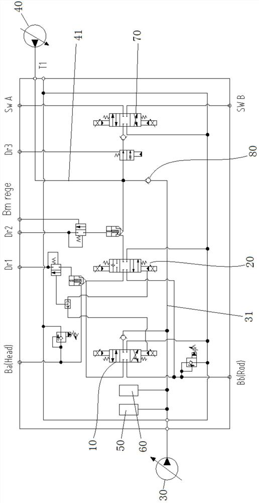
[0004] Therefore, the technical problem to be solved by the present invention is to overcome the defect that the hydraulic system of the excavator in the prior art takes up a large space, thereby providing a hydraulic control system for construction machinery and construction machinery with it

Method used


Image

  • Hydraulic control system of engineering machinery and engineering machinery with hydraulic control system
  • Hydraulic control system of engineering machinery and engineering machinery with hydraulic control system
  • Hydraulic control system of engineering machinery and engineering machinery with hydraulic control system

Examples


Embodiment Construction

[0025]The technical solutions of the present invention will be described below in conjunction with the drawings, as will be described, as described herein is an embodiment of the invention, not all of the embodiments. Based on the embodiments of the present invention, there are all other embodiments obtained without making creative labor without making creative labor premises.

[0026]In the description of the invention, it is to be described in the terms "center", "upper", "lower", "left", "right", "vertical", "horizontal", "within", "outside", etc. The orientation or positional relationship indicated is based on the orientation or positional relationship shown in the drawings, is merely intended to describe the present invention and simplified description, rather than indicating or implying that the device or component must have a specific orientation. Construct and operation, so it is not understood to be the limitation of the invention. Moreover, the term "first", "second", "third"...


PUM


Abstract

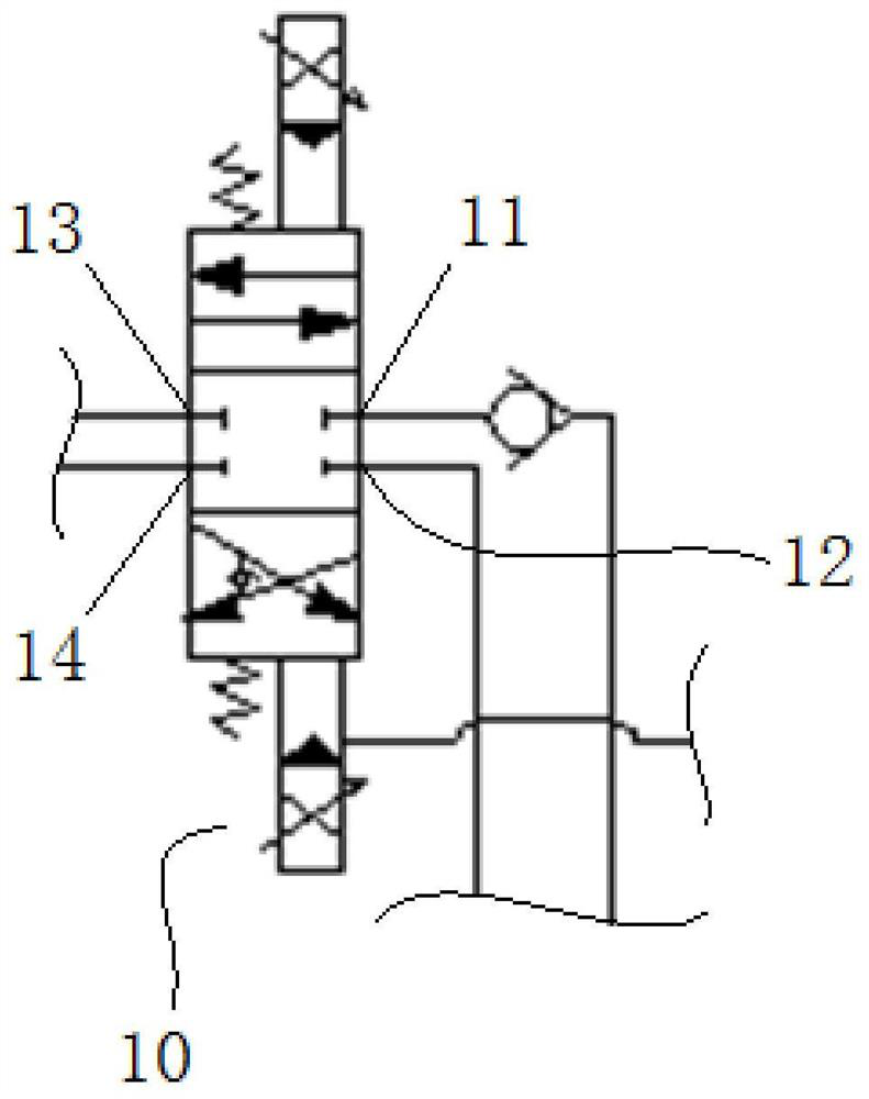
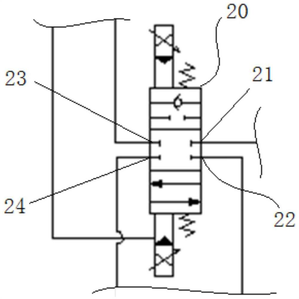
The invention provides a hydraulic control system of engineering machinery and the engineering machinery with the hydraulic control system. The hydraulic control system of the engineering machinery comprises a first control valve and a second control valve, wherein the first control valve comprises a first oil inlet, a first oil discharge outlet, a first working oil port and a second working oil port; the second control valve comprises a second oil inlet, a second oil discharge outlet, a third working oil port and a fourth working oil port; the first working oil port and the third working oil port are suitable for communicating with a rodless cavity of a control oil cylinder of a working device, and the second working oil port and the fourth working oil port are suitable for communicating with a rod cavity of the control oil cylinder; and the first control valve comprises a first gear and a second gear, and the second control valve comprises a third gear and a fourth gear. According to the technical scheme, gravitational potential energy generated when the working device descends can be recycled, and meanwhile the defect that a hydraulic system of an excavator in the prior art is large in occupied space is overcome.

Description

Technical field[0001]The present invention relates to the technical field of excavator equipment, and more particularly to a hydraulic control system for engineering machinery and a construction machinery.Background technique[0002]At present, most engineering mechanical drives are driven by hydraulic pressure. Among them, the hydraulic excavator is a single or composite action by an boom, a hob, a bucket, and a single or composite action. The operator operates the lead handle in the cab, which causes the main valve spool to switch, the oil pump pumps. It is supplied to each working device while the oil supply is discharged from the working device to the fuel tank. Under today's electricity, intelligent trends, the energy saving and price reduction requirements of excavators are increasingly high, and the effective utilization of energy has become one of the important indicators of evaluation excavators. Since the weight of the excavation motor arm work is large, there is a problem w...

Claims


Application Information

Patent Timeline
IPC IPC(8): F16L3/10F15B13/02F15B1/02F15B21/00
CPCF15B1/02F15B13/02F15B21/00F16L3/10
Inventor 王博刘毅徐浩祯宋超郑诗强
Owner SUOTE TRANSMISSION EQUIP
Learn More