
Adjustable throttling device

A throttling device and adjustable technology, applied in the direction of pipes/pipe joints/fittings, mechanical equipment, pipe components, etc., can solve problems such as structural changes, unstable outflow coefficients, and impurity deposition

Pending Publication Date: 2021-05-18
SHANGHAI KAIQUAN PUMP IND GROUP
View PDF0 Cites 0 Cited by
  • Summary
  • Abstract
  • Description
  • Claims
  • Application Information

AI Technical Summary

Problems solved by technology

[0002] At present, the traditional throttling orifice flowmeter is used for specific working conditions. When the working conditions change, the follow-up device needs to be redesigned, and it is prone to step pressure drop and cavitation. When measuring high-temperature and high-pressure fluids, The structure of the throttling orifice flowmeter is easy to deform, and it is prone to structural changes caused by cavitation, which makes the outflow coefficient unstable and the measurement accuracy is not high; impurities are easy to deposit in the orifice plate; the outlet flow field is disordered, etc.

Method used


Image

  • Adjustable throttling device
  • Adjustable throttling device
  • Adjustable throttling device

Examples


Embodiment Construction

[0032] The preferred embodiments of the present invention are given below in conjunction with the accompanying drawings to describe the technical solution of the present invention in detail.

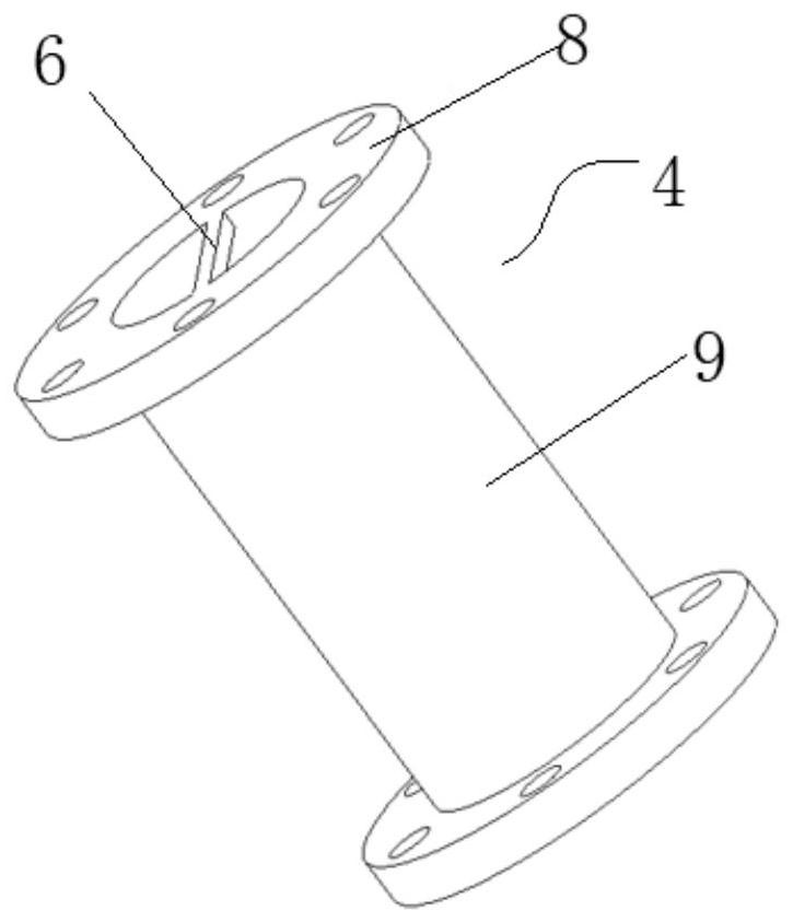
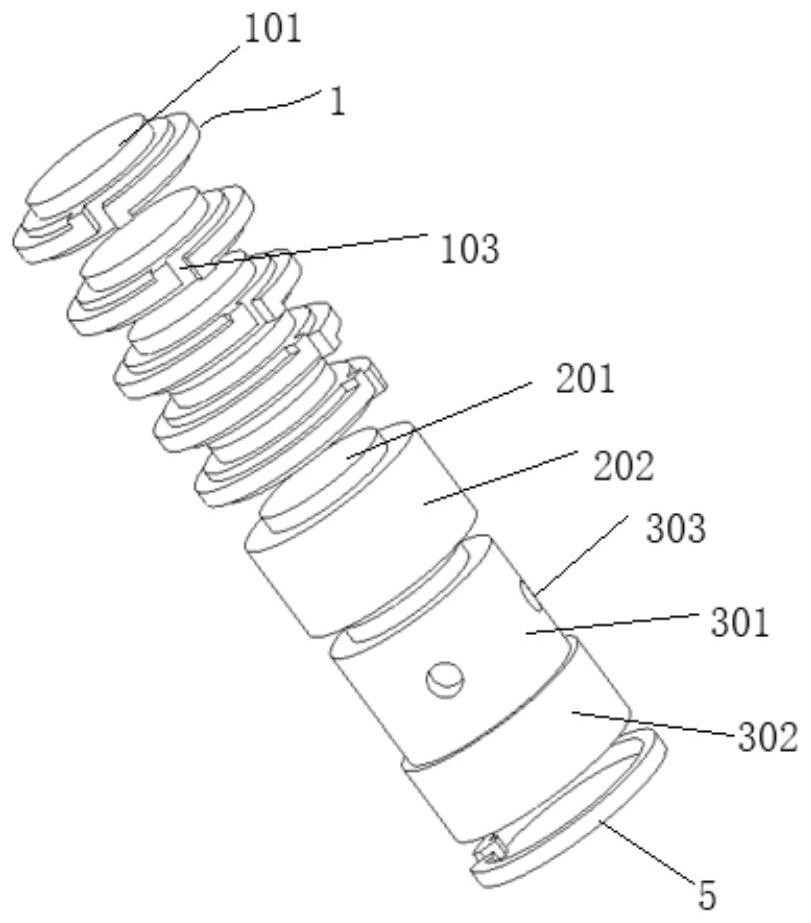
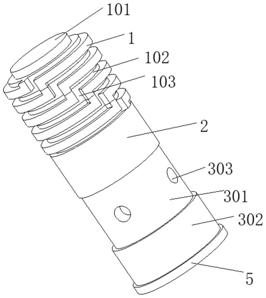
[0033] figure 1 It is a structural schematic diagram of the outer casing of the present invention, diagram 2-1 For the exploded view of other constructions after removing the outer casing of the present invention, Figure 2-2 for diagram 2-1 Schematic diagram of the structure after assembly, Figure 2-3 for diagram 2-1 longitudinal sectional view of Figure 2-4 for Figure 2-2 longitudinal sectional view of image 3 It is a structural schematic diagram of the fluid flow direction of the present invention. As shown in the above figure: the adjustable throttling device provided by the present invention, the adjustable throttling device includes: an outer sleeve 4, a number of first inner stems 1, a second inner stem 2, a third inner stem Stem 3, a limit snap ring 5, a limit rib ...


PUM


Abstract

The invention relates to an adjustable throttling device which comprises an outer sleeve, a plurality of first inner core columns, a second inner core column, a third inner core column, a limiting clamping ring, a limiting rib and a limiting clamping ring. The first inner core columns, the second inner core columns and the third inner core columns are sequentially and fixedly connected in the axial direction through positioning bosses and positioning grooves and then are axially positioned through the outer sleeve, the limiting ribs on the outer sleeve and the limiting clamping ring. The outer diameter of the second inner core column is smaller than that of the first inner core column, the third inner core column comprises an open cylinder part and a hollow cylinder part, and the outer diameter of the hollow cylinder part is larger than that of the open cylinder part. When the pressure reduction requirement is changed, redesign is not needed, the number of the first inner core columns, the diameter of the outer cylinder of the second inner core column and the number and hole diameter of the throttling holes in the third inner core column are determined and selected only through simple calculation, and the purpose that one set of device is reused is achieved.

Description

technical field [0001] The invention relates to a throttling device, in particular to a device that does not need to be redesigned when the demand for pressure reduction changes, but only needs to be calculated simply to determine the number of the first inner core column, and to determine the diameter and diameter of the second inner core column and the outer cylinder. The number and diameter of the throttling holes on the third inner core column are adjustable throttling devices for the purpose of reusing a set of devices. Background technique [0002] At present, the traditional throttling orifice flowmeter is used for specific working conditions. When the working conditions change, the follow-up device needs to be redesigned, and it is prone to step pressure drop and cavitation. When measuring high-temperature and high-pressure fluids, The structure of the throttling orifice flowmeter is easy to deform, and it is prone to structural changes caused by cavitation, which ma...

Claims


Application Information

Patent Timeline
IPC IPC(8): F16L55/027
CPCF16L55/027F16L55/02754
Inventor 杨明芦洪钟唐钧侯多华彭耀
Owner SHANGHAI KAIQUAN PUMP IND GROUP
Learn More