Distribution box for keeping off rain by using folding structure

A technology of folding structure and distribution box, which is applied in substation/power distribution device housing, electrical components, substation/switch layout details, etc., which can solve the problems of poor moisture-proof and rain-proof effect, damage to power equipment in power distribution cabinet, and leakage of electricity, etc. question

Active Publication Date: 2021-05-18
STATE GRID ZHEJIANG ELECTRIC POWER COMPANY TAIZHOU POWER SUPPLY
View PDF14 Cites 0 Cited by
  • Summary
  • Abstract
  • Description
  • Claims
  • Application Information

AI Technical Summary

Problems solved by technology

[0002] The power distribution cabinet is an important facility in the power system. There are a large number of power equipment installed in it. In order to ensure the normal operation of the power equipment, the power distribution cabinet needs to have certain ventilation, heat dissipation, moisture-proof and waterproof functions. Ventilation and heat dissipation are done very well, but the moisture-proof and waterproof functions are poor. The outdoor power distribution cabinets in the prior art have poor moisture-proof and rain-proof effects. If the amount of rainwater is large, it is easy to enter the inside of the power distribution cabinet, which will not only cause damage to the electrical equipment inside the power distribution cabinet, but also easily cause leakage problems. Therefore, a power distribution box that uses a folding structure to protect against rain is designed to solve the problem. this problem

Method used


Image

  • Distribution box for keeping off rain by using folding structure
  • Distribution box for keeping off rain by using folding structure
  • Distribution box for keeping off rain by using folding structure

Examples


Embodiment Construction

[0027] The following will clearly and completely describe the technical solutions in the embodiments of the present invention with reference to the accompanying drawings in the embodiments of the present invention. Obviously, the described embodiments are only some, not all, embodiments of the present invention.

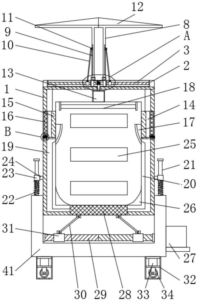
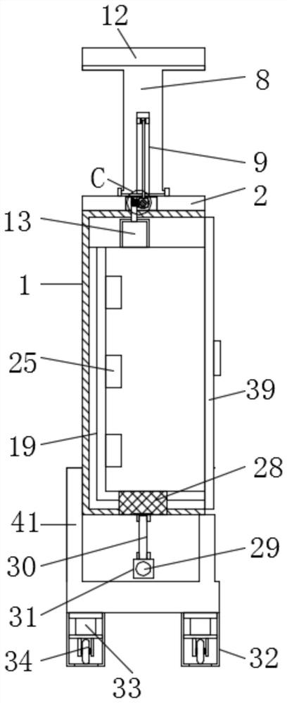
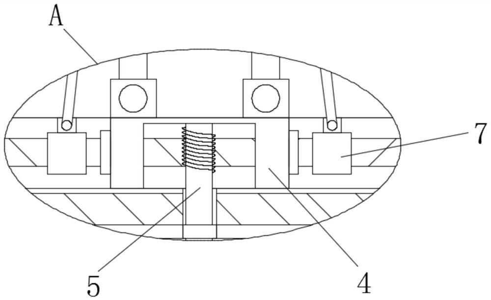
[0028] refer to Figure 1-8 , a power distribution box using a folding structure for rain protection, including a cabinet body 1, the upper end of the cabinet body 1 is connected with a cover plate 2, the upper end of the cover plate 2 is provided with a groove, and the inner middle of the groove is provided with a connecting seat 4 A first reciprocating screw rod 3 is interspersed in the middle of the inner side of the connecting seat 4. The first reciprocating screw rod 3 runs through the groove and extends to both sides to connect with the cover plate 2. The first reciprocating screw rod 3 is located at the center of the connecting seat 4. The middle part of the i...


PUM


Abstract

The invention relates to the technical field of power equipment, in particular to a distribution box for keeping off rain by using a folding structure; the distribution box comprises a cabinet body, the upper end of the cabinet body is connected with a cover plate, the upper end of the cover plate is provided with a groove, the middle part of the inner side of the groove is provided with a connecting seat, and the middle part of the inner side of the connecting seat is transversely inserted with a first reciprocating lead screw; the first reciprocating lead screw penetrates through the groove and extends to the two sides of the groove to be connected with the cover plate, the portion, located in the middle of the inner side of the connecting base, of the first reciprocating lead screw is fixedly sleeved with a turbine, and the left side and the right side of the first reciprocating lead screw are both sleeved with first threaded blocks in a threaded mode. L-shaped flashing boards are movably connected to the left side and right side of the upper end of the connecting seat through first connecting pieces correspondingly. Compared with the prior art, the distribution box has the advantages that the structure is reasonable, the rainproof and moistureproof effects are good, the cabinet body is prevented from being soaked by rainwater, the use effect of the power distribution box for shielding rain by using the folding structure is better, and the practicability is high.

Description

technical field [0001] The invention relates to the technical field of electric equipment, in particular to a power distribution box that uses a folding structure to protect against rain. Background technique [0002] The power distribution cabinet is an important facility in the power system. There are a large number of power equipment installed in it. In order to ensure the normal operation of the power equipment, the power distribution cabinet needs to have certain ventilation, heat dissipation, moisture-proof and waterproof functions. Ventilation and heat dissipation are done very well, but the moisture-proof and waterproof functions are poor. The outdoor power distribution cabinets in the prior art have poor moisture-proof and rain-proof effects. If the amount of rainwater is large, it is easy to enter the inside of the power distribution cabinet, which will not only cause damage to the electrical equipment inside the power distribution cabinet, but also easily cause le...

Claims


Application Information

Patent Timeline
Patent Type & Authority Applications(China)
IPC IPC(8): H02B1/28H02B1/52H02B1/54
CPCH02B1/28H02B1/52H02B1/54Y02A30/14
Inventor 张靖
Owner STATE GRID ZHEJIANG ELECTRIC POWER COMPANY TAIZHOU POWER SUPPLY
Why Eureka
Try Eureka