
Motor control method and device and electronic device

A motor control and circuit technology, which is applied in the field of devices, electronic equipment, and motor control methods, and can solve problems such as inaccurate encoder rotor position angles, etc.

Active Publication Date: 2021-05-18
HANGZHOU OPTIMAX TECH
View PDF4 Cites 1 Cited by
  • Summary
  • Abstract
  • Description
  • Claims
  • Application Information

AI Technical Summary

Problems solved by technology

[0004] The purpose of the embodiment of the present invention is to provide a motor control method, device and electronic equipment to solve the problem of inaccurate rotor position angle caused by encoder angle offset

Method used


Image

  • Motor control method and device and electronic device
  • Motor control method and device and electronic device
  • Motor control method and device and electronic device

Examples


Embodiment Construction

[0025] Embodiments of the present invention provide a motor control method, device and electronic equipment.

[0026] In order to enable those skilled in the art to better understand the technical solutions in the present invention, the technical solutions in the embodiments of the present invention will be clearly and completely described below in conjunction with the drawings in the embodiments of the present invention. Obviously, the described The embodiments are only some of the embodiments of the present invention, not all of them. Based on the embodiments of the present invention, all other embodiments obtained by persons of ordinary skill in the art without creative efforts shall fall within the protection scope of the present invention.

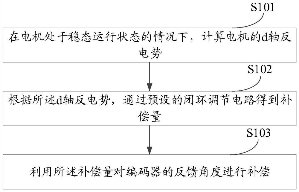
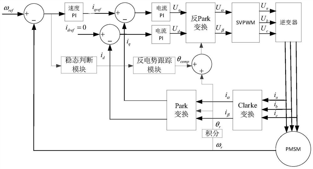
[0027] Such as figure 1 , figure 2 , image 3 As shown, the embodiment of the present invention provides a motor control method, and the execution body of the method may be a motor control unit. The method specifically may includ...


PUM


Abstract

The embodiment of the invention provides a motor control method and device and an electronic device, and the method comprises the steps of calculating the d-axis counter electromotive force of a motor under the condition that the motor is in a steady-state operation state; according to the d-axis counter electromotive force, obtaining a compensation amount through a preset closed-loop adjusting circuit; and compensating a feedback angle of an encoder by using the compensation amount. According to the embodiment of the invention, the fault-tolerant operation of the motor can be realized under the condition that the encoder is not replaced, and the fault-tolerant rate of a system is improved.

Description

technical field [0001] The invention relates to the technical field of automatic control, in particular to a motor control method, device and electronic equipment. Background technique [0002] Modern elevator traction hosts mostly use permanent magnet synchronous motors to drive the car, and permanent magnet synchronous motors under vector control are very dependent on the accuracy of the rotor position. The rotor position angle is generally obtained by feedback from the encoder, and accurate rotor position angle feedback can Guaranteed high-performance control of the motor. [0003] However, when the encoder angle shifts, for example, the encoder loses pulses or the mechanical angle shifts, the position angle of the feedback is inaccurate, which will cause an angle difference between the d-axis of the current and the d-axis of the rotor. Harmonics are generated, causing the current to increase, and the angle difference may continue to accumulate, and the motor shows a con...

Claims


Application Information

Patent Timeline
Patent Type & Authority Applications(China)
IPC IPC(8): H02P21/18H02P6/182
CPCH02P21/18H02P6/182H02P2203/03H02P2207/05Y02B50/00
Inventor 魏晓超赵银波黄其福
Owner HANGZHOU OPTIMAX TECH
Learn More