Moisture-proof sensor and use method thereof
A sensor and sensor body technology, applied in the field of sensors, can solve the problems of poor heat dissipation performance of sensors, easy to be damaged by moisture, etc.
- Summary
- Abstract
- Description
- Claims
- Application Information
AI Technical Summary
Problems solved by technology
Method used
Image

Examples
Embodiment 1
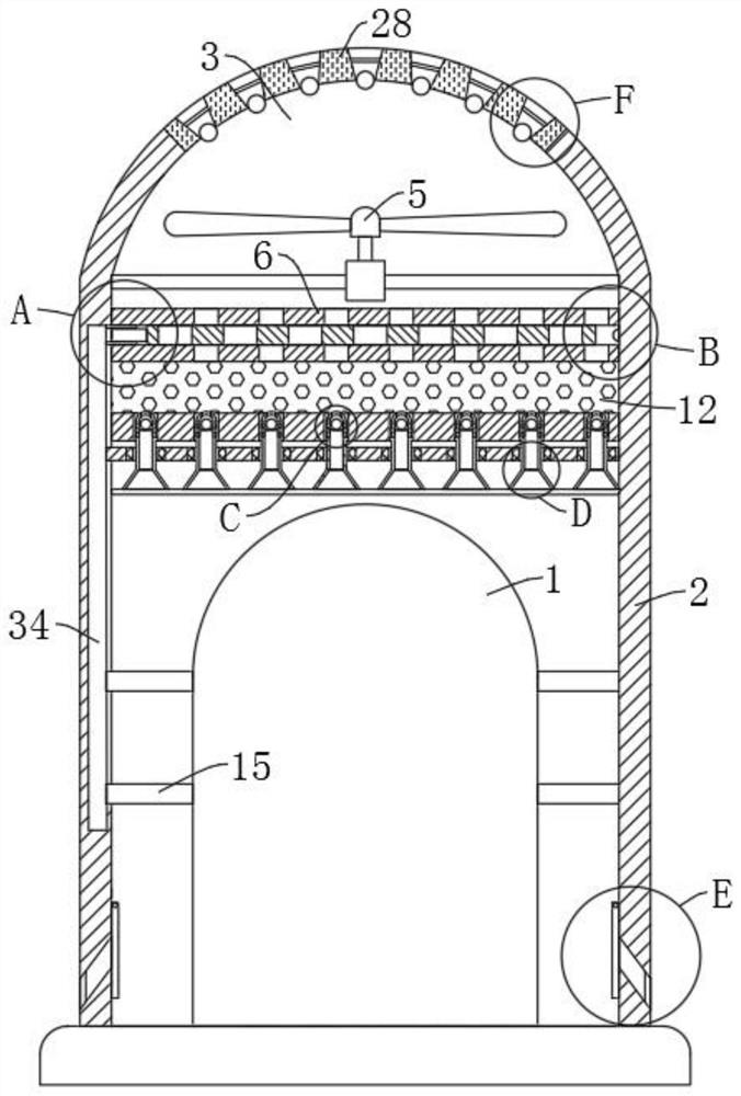
[0041] refer to Figure 1-7, a moisture-proof sensor, including a sensor body 1, the outer wall of the upper end of the sensor body 1 is provided with a protective cover 2, the upper end of the protective cover 2 is provided with a cooling groove 3, and the lower end side wall of the protective cover 2 is provided with a plurality of suction grooves 4. A heat dissipation fan 5 is fixedly installed in the heat dissipation groove 3. Two parallel first flat plates 6 are fixedly connected to the inner wall of the protective cover 2. The two first flat plates 6 are located at the lower end of the heat dissipation fan 5. The two first flat plates The upper ends of the 6 are provided with a plurality of corresponding first through holes 7, the lower ends of the two first flat plates 6 are provided with a second flat plate 10 fixedly connected with the protective cover 2, and the upper ends of the second flat plates 10 are provided with a plurality of uniform Distributed second throug...
Embodiment 2
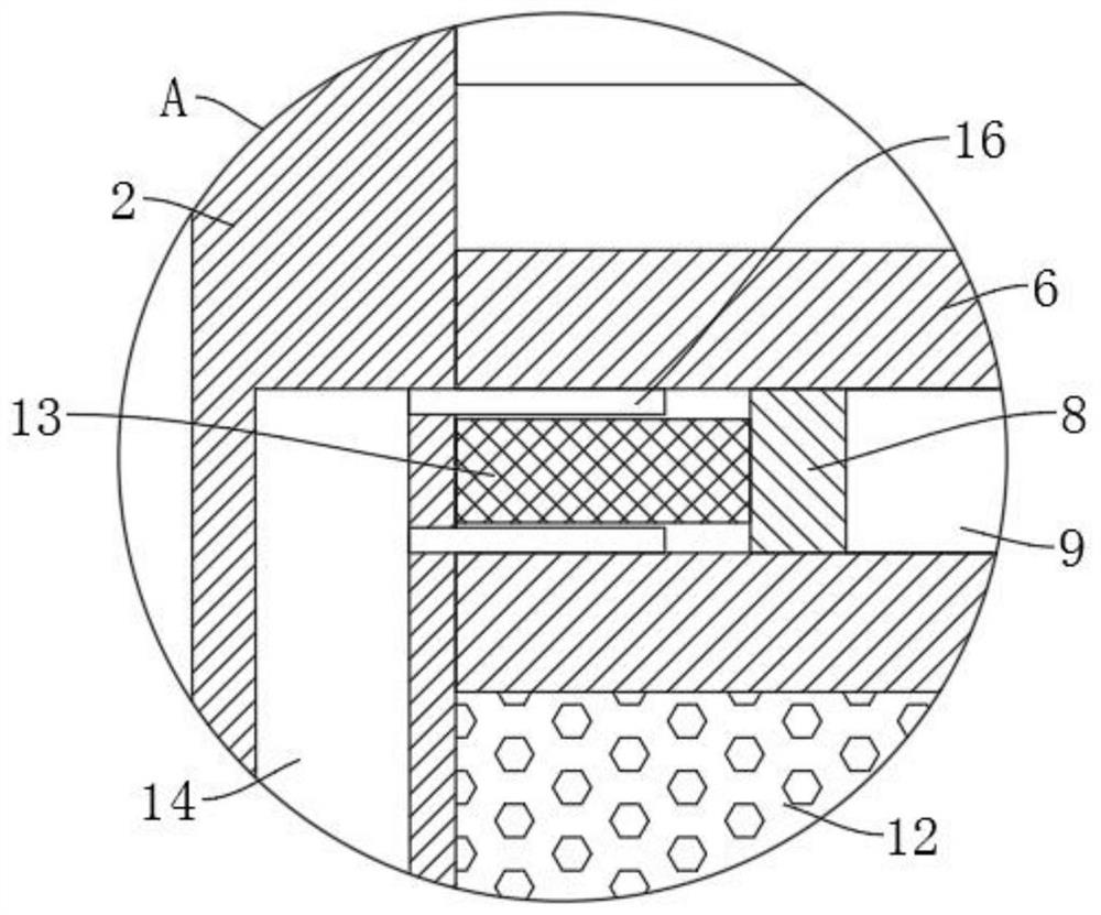
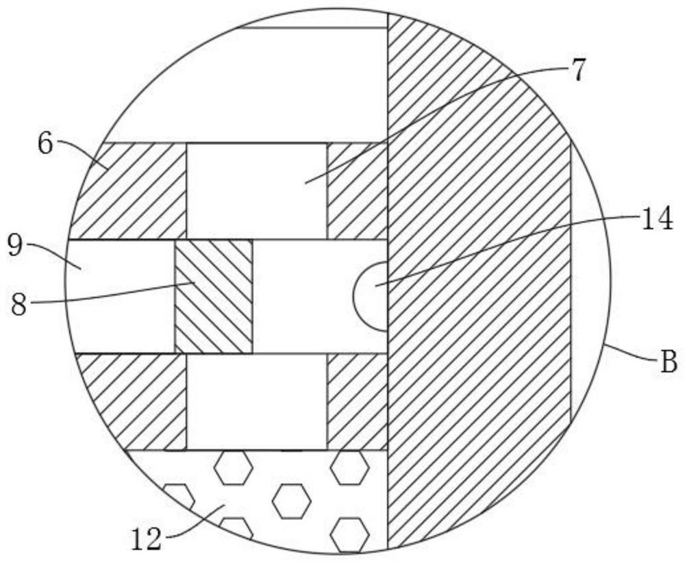
[0046] refer to Figure 1-3 , which is basically the same as in Embodiment 1, furthermore: the automatic opening and closing mechanism includes a third slide plate 8 slidably connected between the two first flat plates 6, and the upper end of the third slide plate 8 is provided with a corresponding to the first through hole 7 a plurality of third through holes 9, the left end of the third slide plate 8 is fixedly connected with an inflatable airbag 13, and the inflatable airbag 13 is fixedly connected on the inner wall of the protective cover 2, and the inner wall of the protective cover 2 is fixedly connected with the first heat conducting rod 34, and the inflatable airbag The upper and lower side walls of 13 are provided with heat conduction plates 16 fixedly connected with the first flat plate 6, both heat conduction plates 16 are fixedly connected with the first heat conduction rod 34, and the side walls of the sensor body 1 are fixedly connected with a plurality of heat co...
Embodiment 3
[0048] refer to Figure 4-5 , is basically the same as Embodiment 1, furthermore: the ejector mechanism includes an end cap 17 sleeved in the second through hole 11, the upper end of the end cap 17 is provided with a fourth through hole 18, the fourth through hole 18 The inner walls on both sides are provided with strip grooves 21, the inner top of the end cover 17 is provided with a first sphere 20 corresponding to the fourth through hole 18, and the lower end of the first sphere 20 is provided with a hollow bottom plate fixedly connected to the inner wall of the end cover 17 19. The outer peripheral wall of the end cover 17 is provided with a plurality of air outlet holes 22, and the side walls of the protective cover 2 are fixedly connected with a hollow limit plate 23 matched with the lower end of the end cover 17. When the hot air passes through the second through hole 11, The hot air will pass through the end cover 17 so that the fourth through hole 18 is exhausted upwar...
PUM
 Abstract
Description
Claims
Application Information
 - R&D
- Intellectual Property
- Life Sciences
- Materials
- Tech Scout
- Unparalleled Data Quality
- Higher Quality Content
- 60% Fewer Hallucinations
Browse by: Latest US Patents, China's latest patents, Technical Efficacy Thesaurus, Application Domain, Technology Topic, Popular Technical Reports.
© 2025 PatSnap. All rights reserved.Legal|Privacy policy|Modern Slavery Act Transparency Statement|Sitemap|About US| Contact US: help@patsnap.com