
Laminating roller

A lamination roller, lamination machine technology, applied in the direction of lamination, lamination device, control lamination, etc., to achieve the effects of prolonging service life, improving heating control, and preventing wear

Inactive Publication Date: 2021-05-25
VIVID LAMINATING TECH
View PDF0 Cites 0 Cited by
  • Summary
  • Abstract
  • Description
  • Claims
  • Application Information

AI Technical Summary

Problems solved by technology

But such non-contact temperature sensors have not been used in laminators because they have problems when the object whose temperature is being measured has a highly reflective surface (like when using rotating chrome lamination rolls)

Method used


Image

  • Laminating roller

Examples


Embodiment Construction

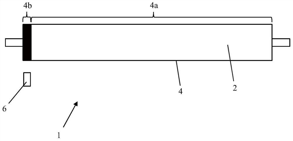
[0017] The laminator 1 comprises heated lamination rolls 2 for bringing into contact a workpiece, such as a sheet to be laminated, by bringing a film of laminate material into adhesive contact with the surface of the sheet.

[0018] The cylindrical outer surface 4 of the laminating roll 2 comprises a wear-resistant and highly reflective chrome-plated surface region 4a. A non-reflective (or matte) surface region 4b is provided at one axial end of the lamination roll 2 . The non-reflective surface region 4b may comprise a strip or band of suitable non-reflective material arranged in an annular groove or channel (not shown) in the outer surface of the laminating roll 2 so that the non-reflective material The outer surface is flush with the outer surface of the chromed surface area 4a. The strip or strip of non-reflective material is about 1-2 centimeters (cm) wide. Alternatively, the non-reflective surface region 4b may comprise a thin layer or coating of a suitable non-reflect...


PUM


Abstract

A laminator includes a laminating roller. A cylindrical outer surface of the laminating roller comprises a reflective (e.g., chrome plated) surface region and a non-reflective surface region. A non-contact temperature sensor is spaced apart from the laminating roller in the radial direction and aligned with the non-reflective surface region of the laminating roller in the axial direction to provide accurate temperature measurements of the non-reflective surface region.

Description

technical field [0001] The present invention relates to laminating rolls, and more particularly to heated laminating rolls, adapted to be rotatably mounted in laminating machines and used for laminating workpieces, for example for adhering vinyl or other similar coatings to workpiece surface. Background technique [0002] Laminators typically include at least one lamination roll, and if the lamination roll is heated, the laminator must be able to control the heating to continuously maintain a user-determined lamination temperature. This often requires that the temperature of the lamination rolls be accurately measured. Heated lamination rolls are typically chrome-plated rolls (ie, their outer surface includes a layer of chrome or a chrome alloy), which means they are relatively wear-resistant and have good heat capacity. This also means that the outer surface of the lamination roll is highly reflective. [0003] The temperature of the heated lamination roll is usually mea...

Claims


Application Information

Patent Timeline
Patent Type & Authority Applications(China)
IPC IPC(8): B21B27/06B21B38/00
CPCB21B27/06B21B38/006B32B37/0053B32B41/00B32B38/1825B32B2309/02
Inventor G·沃德
Owner VIVID LAMINATING TECH
Learn More