Continuous image-text splicing method for ink-jet printer

An inkjet printer, graphics and text technology, applied to the printing device, printing and other directions, can solve the problems of easy deviation of the paper feeding device, affect the visual effect, and the printing image deviates from the printing position, etc., to improve the printing resolution and the vividness of the color , improve printing quality, and ensure the effect of inkjet printing quality

Pending Publication Date: 2021-05-25
北京亚美科软件有限公司
View PDF10 Cites 3 Cited by
  • Summary
  • Abstract
  • Description
  • Claims
  • Application Information

AI Technical Summary

Problems solved by technology

[0004] In the actual application of printing some variable data, such as bills, multiple small pages can be printed on each desktop, and the printing information on each page is different. The identification information is pre-printed on the medium before printing. During the transmission process, the error of the pressure sensor that detects the paper feeding speed, the change of the paper tension during the printing process, etc. will cause the media to stretch, and the paper feeding device is prone to deviation during transmission. If every desktop printing relies on software If the pre-set coordinates are used to spray ink at the same position, errors may occur, which will make the printed image deviate from the proper printing position and affect the visual effect

Method used

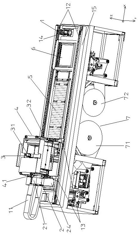
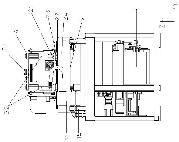
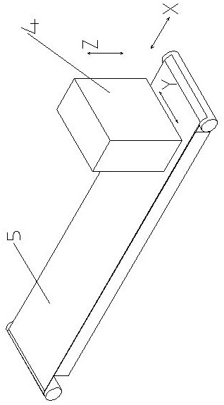

Image

  • Continuous image-text splicing method for ink-jet printer
  • Continuous image-text splicing method for ink-jet printer
  • Continuous image-text splicing method for ink-jet printer

Examples


Embodiment 1

[0049] In this embodiment, the detection device 42 uses a sensor. The sensor is triggered when it passes the mark on the lower medium during the movement process and feeds back the position information here. The software uses the actual position information detected by the sensor to perform the first inkjet printing process. Error correction in the direction (X-axis direction).

[0050] first according to Figure 7 The detection of the logo by the sensor is described. The color of the logo needs to be different from the color of the printing medium. Here, the black rectangle logo is still taken as an example for illustration. During the movement of the printing carriage in the first direction (X-axis direction), the sensor installed on the left end of the printing carriage detects the mark on the medium below. When it reaches the start position of the edge of the black rectangle mark, the sensor is triggered, feedbacks the rising edge signal and remains high. level until the ...

Embodiment 2

[0056] In this embodiment, the detection device 42 uses a camera, and the software pre-calculates the position information of the trigger signal for controlling the camera to take pictures. After receiving the trigger signal, take a photo of the logo below, and the software will perform image recognition on the photo taken, calculate the actual location parameters of the logo, and feed back the location parameters to the control system to control the inkjet corresponding to the nozzle. This detection method, Errors such as stretching or angular deflection in the first direction (X-axis direction), second direction (Y-axis direction), and first direction (X-axis direction) can be corrected for the printed image.

[0057] The following is based on Figure 10 Describe in detail the motion process of the printer detected by the camera. When the media on each table starts printing, the printing carriage is located at the initial end on the right side of the first direction (X-axis ...


PUM


Abstract

The invention provides a continuous image-text splicing method for an ink-jet printer. The method comprises a printing trolley, a paper feeding mechanism and a control system, wherein the printing trolley is provided with printing nozzles; the printing nozzles move back and forth along with the printing trolley in a first direction; the paper feeding mechanism intermittently conveys a medium in the first direction at a paper feeding distance of one desktop each time; the control system is used for controlling the printing trolley, the paper feeding mechanism and the printing nozzles to work; a camera is installed at the side of the printing trolley; marks are printed on the medium in advance, and the theoretical positions of the marks are calculated by software in advance; and in the actual printing process, the camera detects and feeds back the actual positions of the marks on the medium, the software calculates parameters according to the actual positions and the theoretical positions of the marks, and the control system prints the images and texts matched with the actual positions of the marks through the parameters. According to the method, when the coil medium with continuous images and texts is printed, the position error of the medium can be corrected, and accurate position printing of each page of to-be-printed images and texts on each desktop is achieved.

Description

technical field [0001] The invention relates to a continuous image-text splicing method for an ink-jet printer, in particular to a continuous image-text splicing method for an ink-jet printer used for intermittently feeding coil printing media. Background technique [0002] Inkjet printing technology refers to the technology of spraying ink droplets on the printing medium through the nozzle to print images or characters. This technology is non-contact printing, which has the advantages of fast printing speed, low pollution, and adaptability to various printing media, so it is widely used in industrial applications. Inkjet printing is divided into scanning inkjet printing and one pass inkjet printing according to the movement mode of printing car and printing medium. Scanning inkjet printing includes roll-to-roll inkjet printing and flat printing. There are two types of desktop inkjet printing. In the roll-to-roll inkjet printing, the printing carriage moves back and forth a...

Claims


Application Information

Patent Timeline
Patent Type & Authority Applications(China)
IPC IPC(8): B41J2/01B41J11/00B41J29/38
CPCB41J2/01B41J11/008B41J29/38
Inventor 张原张征宇王春瑞
Owner 北京亚美科软件有限公司
Why Eureka
Try Eureka