Active suspension of automobile engine

A technology for automotive engines and active mounts, which is applied to power plants, vehicle components, jet propulsion devices, etc., can solve the problems of reducing low-frequency and large-value vibrations of engine powertrains, poor adaptability, etc., and achieve low mounts Dynamic stiffness, high active power efficiency, and strong adaptability

Active Publication Date: 2021-05-25
ZHUZHOU TIMES NEW MATERIALS TECH
View PDF9 Cites 1 Cited by
  • Summary
  • Abstract
  • Description
  • Claims
  • Application Information

AI Technical Summary

Problems solved by technology

However, the suppression method for low-frequency vibration below 20Hz is still the same as that of traditional liquid resistance mounts, that is, large damping and high dynamic stiffness are generated through the fluid inertial channel, thereby reducing the low-frequency and large-value vibration of the engine powertrain
After the active suspension device is finalized, the performance of the fluid inertial channel is fixed, and no adjustments can be made. This is not very adaptable to the changing conditions of low-frequency vibration.

Method used


Image

  • Active suspension of automobile engine
  • Active suspension of automobile engine
  • Active suspension of automobile engine

Examples


Embodiment 1

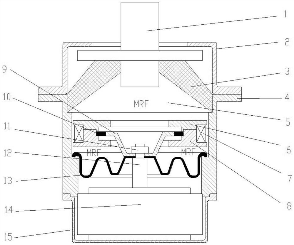
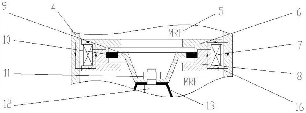
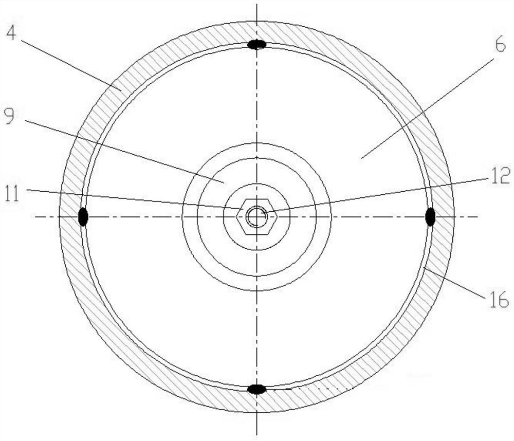
[0030] Such as figure 1 and figure 2 As shown, the automobile engine active mount of this embodiment specifically includes an engine connection section 1, a mount upper shell 2, a rubber main spring 3, a mount middle shell 4, a magnetorheological fluid 5 (MRF), a first bracket 6, Coil 7, second bracket 8, decoupling disk 9, rubber diaphragm 10, nut 11, actuator output rod 12, suspension base film 13, actuator 14, suspension lower shell 15, channel 16.

[0031] In this embodiment, the connecting section 1 of the engine is connected with the power assembly of the engine by bolt connection, and the connecting section 1 of the engine is made of light aluminum alloy. The suspension upper case 2 is used to protect the rubber main spring 3, and the upper part of the suspension upper case 2 can limit the large upward displacement of the engine connecting section 1, so as to avoid the large tensile stress of the rubber main spring 3 and the suspension middle case 4. Disengagement, s...

Embodiment 2

[0049] This embodiment is basically the same as Embodiment 1, the main difference is: as Figure 4 with Figure 5 As shown, in this embodiment, the controllable fluid is the electrorheological fluid 21 , and the fluid control member is an electrode capable of controlling the shear yield strength of the electrorheological fluid 21 in the channel 16 . In this embodiment, the electrorheological fluid 21 (ERF) is used to replace the magnetorheological fluid 5 in Embodiment 1, that is, the first liquid chamber and the second liquid chamber are filled with the electrorheological fluid 21 .

[0050] Since the electrorheological fluid 21 needs an electric field to be controlled, and the structure generated by the electric field is different from the structure generated by the magnetic field, the structure of the corresponding fluid channel 16 in the suspension also needs to be changed.

[0051] In this embodiment, the channel 16 is an annular electrorheological fluid channel 19, the ...

Embodiment 3

[0055] This embodiment is basically the same as Embodiment 1, the main difference is that: in this embodiment, the first liquid chamber is also filled with hydraulic oil rubber capsules, the hydraulic oil rubber capsules are located at a position away from the channel 16, and the hydraulic oil rubber capsules Isolated from controlled fluids.

[0056] In this embodiment, magnetorheological fluid 5 is only used in the magnetorheologically controllable damping channel, while traditional hydraulic oil is used in other parts. This reduces the cost of the suspension and reduces the weight of the active suspension. Put ordinary hydraulic oil in the rubber capsule, and then place the rubber capsule filled with hydraulic oil in the suspended first liquid chamber (that is, the upper liquid chamber), and the hydraulic oil rubber capsule fills a part of the first liquid chamber (that is, the upper liquid chamber). liquid chamber), so that the amount of magnetorheological fluid 5 can be r...


PUM


Abstract

The invention discloses an active suspension of an automobile engine, which comprises a first liquid chamber and a second liquid chamber, a channel communicating the first liquid chamber with the second liquid chamber is arranged between the first liquid chamber and the second liquid chamber, and the channel, the first liquid chamber and the second liquid chamber are filled with controllable fluid. The channel is further provided with a fluid control piece used for controlling the physical performance of the controllable fluid so as to adjust the damping performance of the active suspension. The method has the advantages of being high in adaptability, good in damping effect, good in control effect on low-frequency large-amplitude vibration and the like.

Description

technical field [0001] The invention relates to the technical field of automobile engine mounts, in particular to an automobile engine active mount. Background technique [0002] The automotive engine mount system is an elastic connection system between the engine and the frame or body. Its main functions are: on the one hand, reduce the transmission of engine powertrain vibration to the body, and on the other hand, suppress the overall vibration displacement amplitude of the engine power. These two aspects have completely opposite requirements on the performance of the mount: in order to suppress the large vibration displacement amplitude of the engine powertrain, the mount should have high stiffness and large damping characteristics in the low-frequency vibration range below 20Hz; The vibration transmission rate to the frame or body, in the vibration frequency range above 20Hz, the suspension should have low stiffness and small damping characteristics. Traditional rubber ...

Claims


Application Information

Patent Timeline
Patent Type & Authority Applications(China)
IPC IPC(8): B60K5/12F16F15/03
CPCB60K5/12F16F15/03
Inventor 涂奉臣肖光辉刘少文王里达贺才春查国涛胡金昌张弯弓
Owner ZHUZHOU TIMES NEW MATERIALS TECH
Why Eureka
Try Eureka