Auxiliary laying equipment for fiber cement cable pipe

A technology of fiber cement and cable tubes, which is applied in the installation of cables, cables in underground pipes, electrical components, etc. It can solve the problems of affecting the service life of cables, affecting the normal transmission of power, and large tensile stress of cables. Improve tube efficiency, improve connection performance, and prevent corrosion

Active Publication Date: 2021-05-25
佛山市荣达线缆有限公司
View PDF15 Cites 2 Cited by
  • Summary
  • Abstract
  • Description
  • Claims
  • Application Information

AI Technical Summary

Problems solved by technology

[0003] The cable tube is also known as the cable protection tube. It is mainly installed in the intersection of the communication cable and the power line to prevent the short circuit caused by the disconnection of the power line, which will cause the communication cable and the steel wire rope to be electrified. Traction, to complete the pipe penetration, but the cable is pulled by the tractor, it is easy to cause the local tensile stress of the cable to be too large, and it is easy to cause the cable to break. The cable tube is usually fixed by an external bracket when the cable tube is externally impacted. Due to the looseness between the cable and the cable tube, it is easy to cause damage to the cable and affect the service life of the cable. In addition, in order to meet the long-distance cable laying, the cable tube is often continued to meet the laying requirements. Due to construction errors, it is impossible to ensure that the axes of the adjacent cable tubes are on the same straight line. It is necessary to locally bend the continuous part to ensure that the axes are at the same height. However, the local stress of the bent cable tube is too large, and it is easy to In the underground environment, once broken, the moisture in the soil can easily penetrate, causing the cable to be corroded, affecting the normal transmission of power, and inconvenient to maintain

Method used


Image

  • Auxiliary laying equipment for fiber cement cable pipe
  • Auxiliary laying equipment for fiber cement cable pipe
  • Auxiliary laying equipment for fiber cement cable pipe

Examples


Embodiment Construction

[0031] The following will clearly and completely describe the technical solutions in the embodiments of the present invention with reference to the accompanying drawings in the embodiments of the present invention. Obviously, the described embodiments are only some, not all, embodiments of the present invention. Based on the embodiments of the present invention, all other embodiments obtained by persons of ordinary skill in the art without making creative efforts belong to the protection scope of the present invention.

[0032] The invention provides technical solutions:

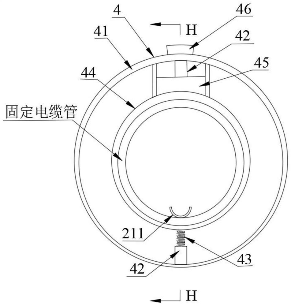
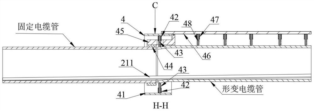
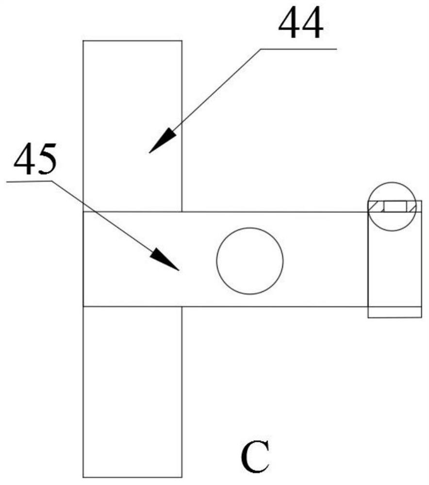
[0033] Such as Figure 1~4 As shown, the fiber cement cable pipe auxiliary laying equipment includes a frame assembly 1, a fixing device 2, a power device 3 and a connecting device 4, the frame assembly 1 and the power device 3 are tightly connected, and one side of the power device 3 is connected to the fixed The device 2 is movably connected, the fixing device 2 is tightly connected to the cable tube 5, o...


PUM


Abstract

The invention discloses auxiliary laying equipment for a fiber cement cable pipe, the auxiliary laying equipment comprises a frame assembly, a fixing device, a power device and a connecting device, and is characterized in that the frame assembly is fixedly connected with the power device, one side of the power device is movably connected with the fixing device, the fixing device is fixedly connected with a cable pipe, one side of the frame assembly is connected with the cable pipe. Every two adjacent cable pipes are connected through the connecting device, each connecting device comprises a connecting sleeve, a transmission spring and a pressing plate, the connecting sleeves are arranged at the connecting positions of the cable pipes in a sleeving mode, the multiple transmission springs are arranged on the outer rings of one ends of the cable pipes, and one ends of the transmission springs are movably connected with the cable pipes. The side, away from the cable pipe, of the transmission spring is fixedly connected with the inner ring wall face of the connecting sleeve, a seat ring is arranged at the joint of the transmission spring and the connecting sleeve, one end of the seat ring is fixedly connected with the inner ring wall face of the connecting sleeve, and the inner ring of the seat ring is movably connected with the outer ring of the transmission spring.

Description

technical field [0001] The invention relates to the technical field of cable pipe laying, in particular to auxiliary laying equipment for fiber cement cable pipes. Background technique [0002] With the development and progress of science and technology, all kinds of high and low voltage cables are widely used in power transmission. Due to the limitation of transmission conditions, some cables are buried underground through cable tubes. Among them, fiberglass cable tubes and fiber cement cable tubes are more widely used. , Fiber cement cable pipe is a masterpiece of domestic power transmission level improvement. It uses high-strength and non-polluting vinylon fiber as the plate material, adds high-strength high-movement vinylon, plant fiber and other raw materials, and uses high-grade cement as the main raw material to form a new generation of reinforced fibers. After the cement cable pipe and fiber cement cable pipe are laid underground, the wet soil makes the hardening pro...

Claims


Application Information

Patent Timeline
Patent Type & Authority Applications(China)
IPC IPC(8): H02G9/06H02G3/06
CPCH02G3/0691H02G9/06
Inventor 夏俊杰
Owner 佛山市荣达线缆有限公司
Why Eureka
Try Eureka