RF power amplifier with balun transformer

A balun transformer, amplifier technology, applied in amplifiers with semiconductor devices/discharge tubes, amplifiers, transformer/inductor components, etc., can solve problems such as increased loss and cost, and achieve high manufacturing quality, reproducibility and reliability. The effect of automated manufacturing quality

Pending Publication Date: 2021-05-25
PRODRIVE TECH INNOVATION SERVICES BV
View PDF4 Cites 2 Cited by
  • Summary
  • Abstract
  • Description
  • Claims
  • Application Information

AI Technical Summary

Problems solved by technology

These power combining and distribution techniques inherently require additional components, which increase losses and cost

Method used


Image

  • RF power amplifier with balun transformer
  • RF power amplifier with balun transformer
  • RF power amplifier with balun transformer

Examples


Embodiment Construction

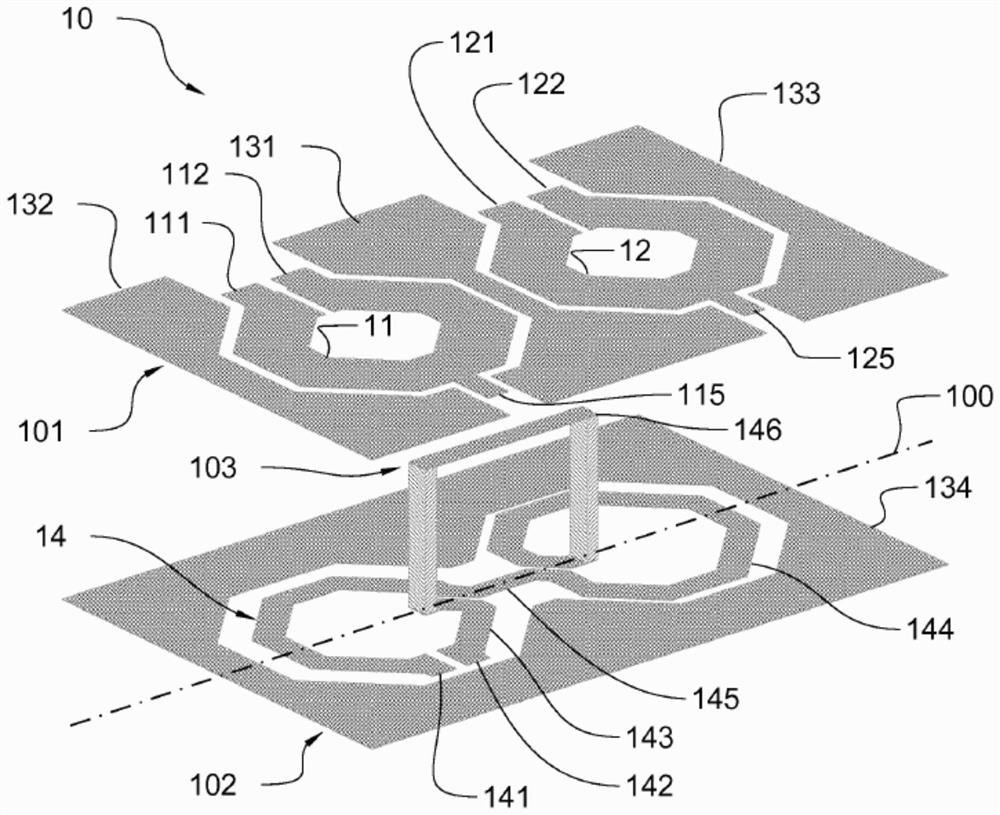
[0039] refer to figure 1 , the balun transformer 10 according to aspects described herein includes a balanced coil 11 and a balanced auxiliary coil 12 in the first plane 101 of the PCB. The balanced and auxiliary coils are made of traces of conductive material and each coil has a first balanced signal terminal 111 , 121 and a second balanced signal terminal 112 , 122 respectively. These first signal terminals 111, 121 and second signal terminals 112, 122 may be connected to a radio frequency AC power supply. Furthermore, each of the coils 11, 12 may comprise a reference port 115, 125 respectively which may be connected to a DC power source (eg DC feed or ground). The first balanced signal terminal 111 , 121 and the second balanced signal terminal 112 , 122 of the balanced coil 11 and the auxiliary coil 12 , respectively, advantageously extend electrically symmetrically from the reference port 115 , 125 . Advantageously, the shielding conductor 131 is placed between the balan...


PUM


Abstract

A radiofrequency power amplifier (60), comprising a balun transformer and a plurality of power transistor pairs (61, 62) arranged in a push-pull configuration. The balun transformer comprises an unbalanced coil (14) extending between a first single-ended signal terminal (142) and a first reference (141), and a balanced coil (11) extending between a first balanced signal terminal (111) and a second balanced signal terminal (112). The balun transformer further comprises at least one auxiliary coil (12) electrically isolated from the unbalanced coil and the balanced coil. The at least one auxiliary coil is inductively coupled to the unbalanced coil (14) and extends between a third balanced signal terminal (121) and a fourth balanced signal terminal(122) forming a balanced combiner-divider.An output of a first one of the plurality of power transistor pairs (61, 62) is coupled to the first and second balanced signal terminals (111, 112) and an output of a second one of the plurality of power transistor pairs (61, 62) is coupled to the third and fourth balanced signal terminals (121, 122).

Description

technical field [0001] The invention relates to a balun (balanced-unbalanced) transformer, which is an electrical component capable of converting an unbalanced signal into a balanced signal and vice versa. The invention more particularly relates to a planar balun. Even more specifically, the present invention relates to a planar balun topology for power combining. The invention further relates to a power amplifier comprising such a balun. The invention also relates to an MRI system comprising such a power amplifier. The invention further relates to a method for power combining. Background technique [0002] Several applications such as Magnetic Resonance Imaging (MRI) require high power levels (eg 2OkW) in the high frequency region (eg 64MHz to 128MHz). Typically, this high power level is achieved by combining multiple smaller power amplifiers. First, two power RF transistors (eg, MOSFETs) are used in a push-pull configuration where a coax transmission line balun is use...

Claims


Application Information

Patent Timeline
Patent Type & Authority Applications(China)
IPC IPC(8): H01F19/06H01F27/04H01F27/28H01F19/04
CPCH01F19/04H01F27/2804G01R33/3614H01P5/10H03F3/195H03F3/245H03F2200/06H03F2200/451H03F2200/537
Inventor B·G·M·范阿尔克
Owner PRODRIVE TECH INNOVATION SERVICES BV
Why Eureka
Try Eureka