
Optical filter, optical filter module and intense pulsed light treatment head

A filter and treatment head technology, applied in the optical field, can solve the problem of inconvenient replacement of the filter, and achieve the effect of convenient switching

Active Publication Date: 2021-05-28
重庆翰恒医疗科技有限公司
View PDF15 Cites 3 Cited by
  • Summary
  • Abstract
  • Description
  • Claims
  • Application Information

AI Technical Summary

Problems solved by technology

[0005] The present invention aims to solve the technical problems existing in the prior art. The first purpose of the present invention is to provide a filter to solve the technical problem of inconvenient replacement of the filter in the prior art

Method used


Image

  • Optical filter, optical filter module and intense pulsed light treatment head
  • Optical filter, optical filter module and intense pulsed light treatment head
  • Optical filter, optical filter module and intense pulsed light treatment head

Examples


Embodiment Construction

[0030] Embodiments of the present invention are described in detail below, and examples of the embodiments are shown in the drawings, wherein the same or similar reference numerals denote the same or similar elements or elements having the same or similar functions throughout. The embodiments described below by referring to the figures are exemplary only for explaining the present invention and should not be construed as limiting the present invention.

[0031] In describing the present invention, it should be understood that the terms "longitudinal", "transverse", "vertical", "upper", "lower", "front", "rear", "left", "right", The orientations or positional relationships indicated by "vertical", "horizontal", "top", "bottom", "inner", "outer", etc. are based on the orientation or positional relationships shown in the drawings, and are only for the convenience of describing the present invention and simplified descriptions, rather than indicating or implying that the device or...


PUM


Abstract

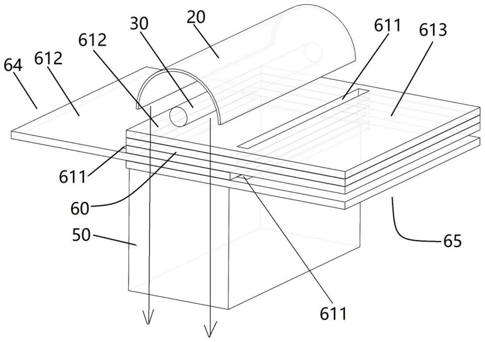
The invention provides an optical filter, an optical filter module and an intense pulsed light treatment head. The optical filter is provided with a slit gap which divides the optical filter into an independent working area and an independent window area. The optical filter module comprises a plurality of layers of stacked optical filters, and the optical filters can be overlapped or staggered by sliding the optical filters; during working, the working area of the adaptive optical filter is located in an optical path, and the window areas of the other optical filters are located in the optical path. The intense pulse light treatment head comprises a treatment head shell, a pulse xenon lamp, a reflecting cover, the optical filter module and a light guide prism; and the optical filter at the lowest layer is in contact with the top surface of the light guide prism. According to the intense pulse light treatment head, when the optical filter needs to be switched, people move the window area of the previous state adaptive optical filter into the optical path and move the working area of the current state adaptive optical filter into the optical path, the optical filter does not need to be taken down, and the optical filter is convenient to switch; and the optical filter does not need to be taken down, so that the risk of optical filter loss is reduced.

Description

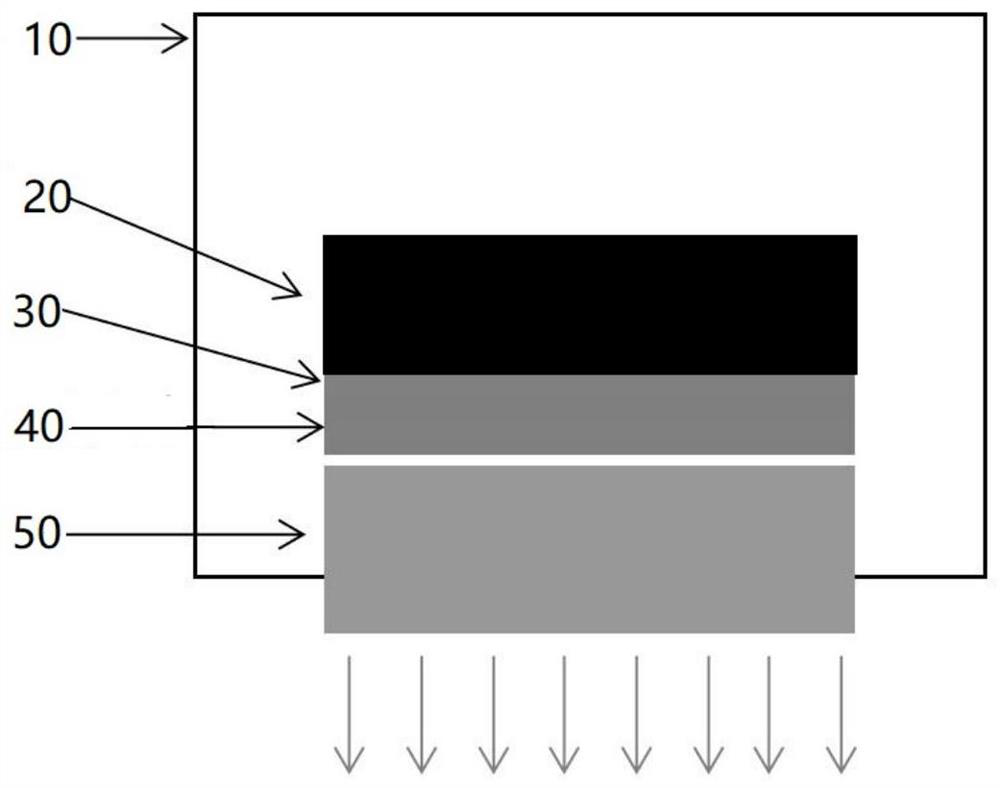
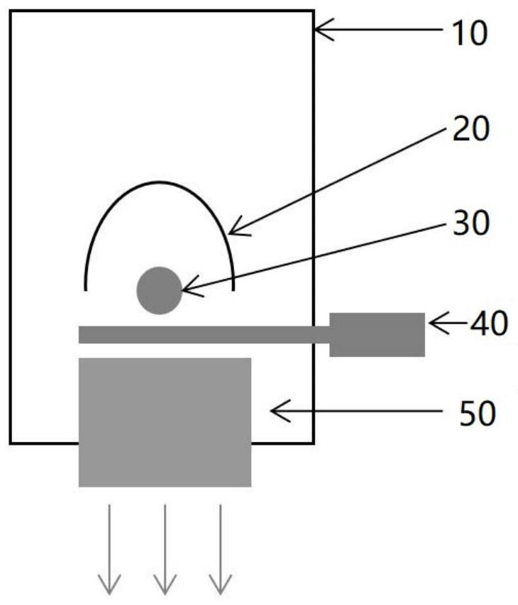
technical field [0001] The invention belongs to the field of optical technology, and in particular relates to an optical filter, an optical filter module and an intense pulsed light therapy head. Background technique [0002] Dry eye is the most common ocular surface disease in my country and the world. Intense Pulsed Light (IPL) Dry Eye Therapeutic Apparatus uses pulsed xenon lamp as the light source, and uses optical filters to screen the spectrum. Through the pulse circuit, a specific wavelength incoherent light pulse with high energy density is emitted. The light pulse has a good curative effect on the inflammation of meibomian glands, abnormal blood vessels, and demodex mites, and can effectively treat dry eye syndrome caused by meibomian gland dysfunction. [0003] attached figure 1 And attached figure 2 It is a typical optical path structure of an existing intense pulsed light treatment head (IPL treatment head), which includes a pulse xenon lamp (30) inside the ...

Claims


Application Information

Patent Timeline
Patent Type & Authority Applications(China)
IPC IPC(8): A61N5/06G02B5/20G02B7/00
CPCA61N5/0613G02B5/20G02B7/006A61N2005/0654A61N2005/0658A61N2005/0659A61N2005/0661A61N2005/0662A61N2005/0664
Inventor 陈驰
Owner 重庆翰恒医疗科技有限公司
Features
  • Generate Ideas
  • Intellectual Property
  • Life Sciences
  • Materials
  • Tech Scout
  • Unparalleled Data Quality
  • Higher Quality Content
  • 60% Fewer Hallucinations
Learn More