Targeted filtering device for high-viscosity gear lubricating oil

A technology of gear lubricating oil and filtering device, which is applied in the direction of filtration and separation, lubricating parts, and engine lubrication, etc. It can solve problems such as poor application effect, increased failure rate of operating machinery, and shedding of metal abrasive particles, and achieves obvious use effects , the effect of strong application adaptability

Pending Publication Date: 2021-05-28
陕西观能机电科技有限公司
View PDF0 Cites 0 Cited by
  • Summary
  • Abstract
  • Description
  • Claims
  • Application Information

AI Technical Summary

Problems solved by technology

[0002] The lubricating oil system needs to maintain clean oil quality. Various complex wear and impacts will inevitably occur when the machine is running, and the metal abrasive particles will fall off and increase gradually. This metal particle is a very harmful substance, and there will be a large amount of metal in the oil system. Particles, the particle size of these particles is very small, there will be more than one million micron-sized metal particles in 100 ml of oil, which will cause excessive wear of rotating parts, and metal particles will cause accelerated oxidation of lubricating oil, eventually Lead to premature oil failure and scrap
[0003] The vast majority of traditional filter devices use filter elements made of fiber material and metal keels. This filter element is characterized by the use of pore-diameter blocking filter principles. This filter method is not effective in high-viscosity and high-flow systems. it is good
The disadvantage of this filter element is that it must be discarded after a period of use, resulting in the generation of hazardous waste
This kind of filter element is unable to achieve high-precision filtration of the lubricating oil system, and cannot improve the cleanliness of the oil, which will inevitably increase the failure rate of the operating machinery, and will also cause accelerated aging and scrapping of the oil.

Method used


Image

  • Targeted filtering device for high-viscosity gear lubricating oil
  • Targeted filtering device for high-viscosity gear lubricating oil
  • Targeted filtering device for high-viscosity gear lubricating oil

Examples


Embodiment Construction

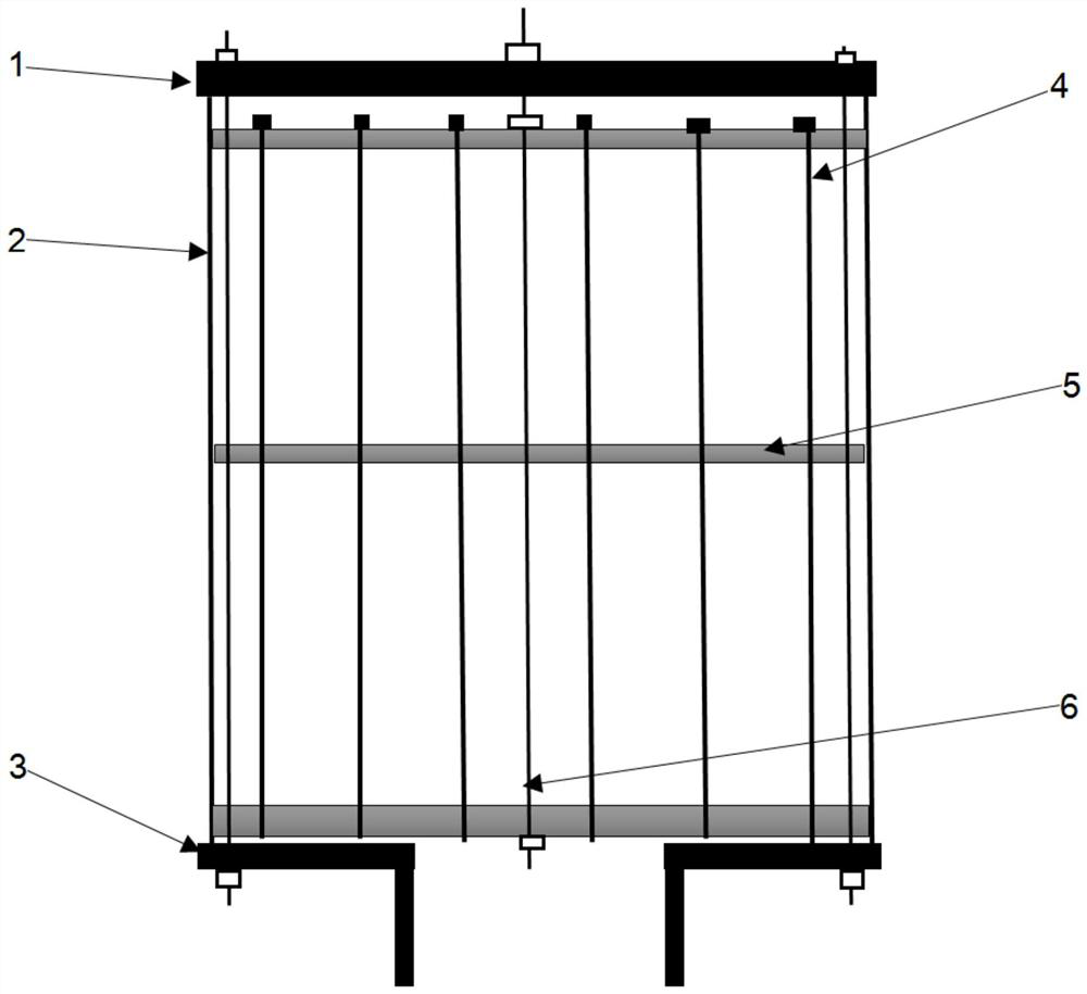
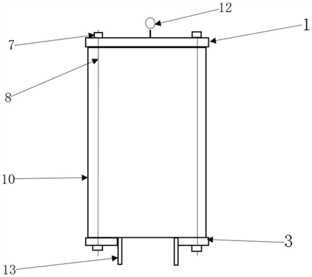
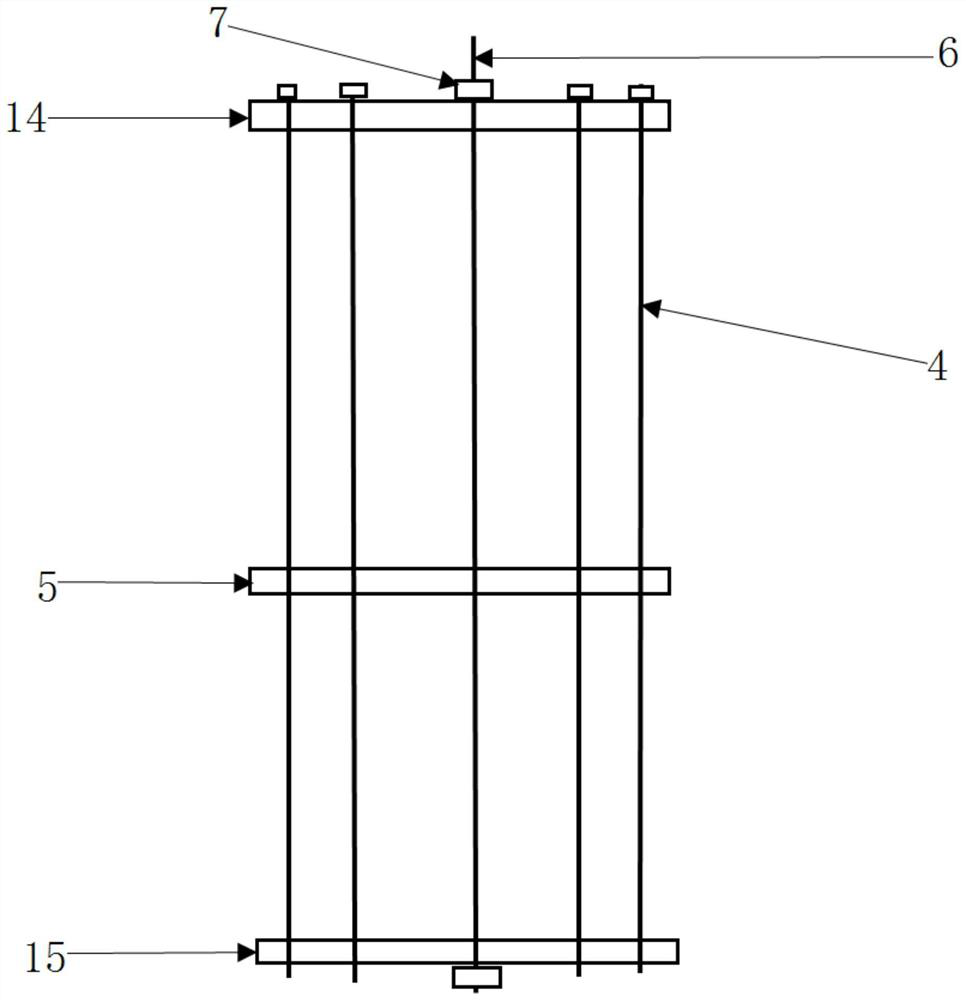
[0036] The following will clearly and completely describe the technical solutions in the embodiments of the present invention with reference to the accompanying drawings in the embodiments of the present invention. Obviously, the described embodiments are some of the embodiments of the present invention, but not all of them. Based on the embodiments of the present invention, all other embodiments obtained by persons of ordinary skill in the art without making creative efforts belong to the protection scope of the present invention.

[0037] In describing the present invention, it should be understood that the terms "center", "longitudinal", "transverse", "upper", "lower", "front", "rear", "left", "right", " The orientation or positional relationship indicated by "vertical", "horizontal", "top", "bottom", "inner", "outer", "side", "end", "side" etc. is based on the Orientation or positional relationship is only for the convenience of describing the present invention and simplif...


PUM

PropertyMeasurementUnit
diameteraaaaaaaaaa
magnetic fieldaaaaaaaaaa

Abstract

The invention discloses a targeted filtering device for high-viscosity gear lubricating oil, which is characterized in that the surface of a cylinder is provided with a coarse filter screen, the upper end and the lower end of the cylinder are respectively provided with a first cover plate and a second cover plate, and the lower end of the second cover plate is provided with an outlet pipe seat; and a second chuck, a first chuck and a third chuck are sequentially arranged in the cylinder from top to bottom, a plurality of magnetic rod units are arranged in the cylinder at intervals in the axial direction of the cylinder and sequentially penetrate through the second chuck, the first chuck and the third chuck, and the flow field range controlled by each magnetic rod unit ranges from 0 mm to 30 mm. And the total through-flow area of the cylinder body is larger than 3-4 times of the through-flow area of the oil pump outlet pipeline. The device has obvious use effect and strong application adaptability, can achieve the purpose of targeted filtration, and does not cause harm to oil liquid due to type selection of filter materials.

Description

technical field [0001] The invention belongs to the technical field of oil quality cleaning, and in particular relates to a targeted filtering device for high-viscosity gear lubricating oil. Background technique [0002] The lubricating oil system needs to maintain clean oil quality. Various complex wear and impacts will inevitably occur when the machine is running, and the metal abrasive particles will fall off and increase gradually. This metal particle is a very harmful substance, and there will be a large amount of metal in the oil system. Particles, the particle size of these particles is very small, there will be more than one million micron-sized metal particles in 100 ml of oil, which will cause excessive wear of rotating parts, and metal particles will cause accelerated oxidation of lubricating oil, eventually Lead to premature oil failure and scrap. [0003] The vast majority of traditional filter devices use filter elements made of fiber material and metal keels....

Claims


Application Information

Patent Timeline
Patent Type & Authority Applications(China)
IPC IPC(8): B03C1/30B01D29/50B01D29/58B01D29/56B01D29/33B01D29/01B01D29/96F16N39/06
CPCB03C1/30B01D29/50B01D29/58B01D29/56B01D29/33B01D29/01B01D29/96F16N39/06B01D29/15
Inventor 李乐李宗霖杜文珍颉小龙常海东岳自维陈宇吴晓峰
Owner 陕西观能机电科技有限公司
Why Eureka
Try Eureka