
Nylon gear lubricating device and lubricating method

A nylon gear and lubricating device technology, which is applied to devices and coatings that apply liquid to the surface, can solve the problems of unstable operation, inconvenient disassembly and installation, wear and baldness of gear tips, etc., to avoid polluting the surrounding environment and improve Lubrication efficiency, the effect of ensuring the lubricating effect

Pending Publication Date: 2021-05-28
NANTONG ZHONGLV GEAR CO LTD
View PDF1 Cites 0 Cited by
  • Summary
  • Abstract
  • Description
  • Claims
  • Application Information

AI Technical Summary

Problems solved by technology

[0002] The role of the gear is to transmit the rotation of one shaft to another shaft. The gear can transmit power, change the speed and change the direction of motion. The nylon gear will not damage the corresponding gear or connecting parts. It has low noise and is widely used in In various industries such as textile, papermaking, printing, machinery, etc., nylon gears are in the process of joint rotation of corresponding gears or connecting parts. Due to dry grinding during operation, the wear of the shaft hole becomes larger, and the corresponding gear tip will also wear and become bald, which is easy to cause rotation. Jumping from time to time, causing damage to the gears, resulting in unstable operation
[0003] At present, in the process of lubricating nylon gears, such as the patent No. 201310493795.X nylon gear lubricating device, nylon gears are installed on both sides of the mandrel, bearing seats are installed on the outer sides of the two ends of the mandrel, and oil filling ports are installed on the inner sides of the two ends of the mandrel. The oil injection ports on both sides of the mandrel are used to lubricate the nylon gears, but the lubricating oil easily leaks from the nylon gears and pollutes the surrounding environment. The nylon gear is set in a lubrication box with a transverse shaft, and the transverse shaft drives the nylon gear to rotate, and sprays lubricating oil to the nylon gear through the spray pipe to lubricate the surface of the nylon gear. However, the lubricating device with this structure exists as follows defect:
[0004] 1. Nylon gears need to be fastened and fixed on the transverse shaft, and the connection is firm. Otherwise, when the transverse shaft rotates at high speed, the nylon gear will be detached from the transverse shaft, which will affect the lubrication effect and even bring safety hazards. Due to the single structure of nylon gears, therefore The nylon gear and the transverse shaft need to be equipped with clips to make them firm, but this structure will inevitably cause inconvenience in disassembly and installation, and the lubrication efficiency of the nylon gear is low;
[0005] 2. If clamping pieces are installed on both sides of the nylon gear to make it firmly connected to the transverse shaft, it will be difficult for lubricating oil to enter the part of the nylon gear located at the clamping piece, and there will be lubricating blind spots, making it impossible to achieve all-round lubrication without dead ends.

Method used


Image

  • Nylon gear lubricating device and lubricating method
  • Nylon gear lubricating device and lubricating method
  • Nylon gear lubricating device and lubricating method

Examples


Embodiment Construction

[0033] In order to deepen the understanding of the present invention, the present invention will be further described below in conjunction with the embodiments and accompanying drawings. The embodiments are only used to explain the present invention and do not constitute a limitation to the protection scope of the present invention.

[0034]In the description of the present invention, it should be understood that the terms indicating orientation or positional relationship, such as based on the orientation or positional relationship shown in the drawings, are only for the convenience of describing the present invention and simplifying the description, rather than indicating or implying the Structures or units must have a specific orientation and thus should not be construed as limiting the invention.

[0035] In the present invention, unless otherwise clearly specified and limited, terms such as "connected", "provided" and "had" should be understood in a broad sense, for example...


PUM


Abstract

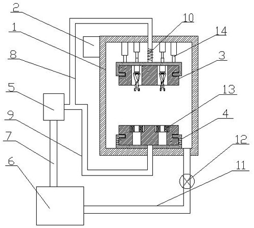
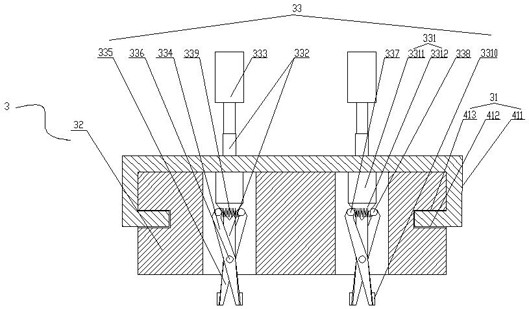
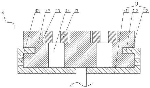
The invention relates to a nylon gear lubricating device. The nylon gear lubricating device comprises an oil injection tank and a control box arranged on the oil injection tank; an upper pressing block assembly and a lower lubricating assembly are arranged in the oil injection tank; an oil pump is arranged outside the oil injection tank, and the oil pump is connected with an oil storage tank through a pipeline; the oil pump is connected with the upper pressing block assembly and the lower lubricating assembly through a first connecting branch pipe and a second connecting branch pipe respectively; a telescopic section is arranged at the position, close to the upper pressing block assembly, of the first connecting branch pipe; the oil injection tank communicates with the oil storage tank through an oil outlet pipeline; a valve is arranged on the oil outlet pipeline; and the control box is electrically connected with the oil pump, the upper pressing block assembly and the valve in sequence. The nylon gear lubricating device has the following advantages that multiple nylon gears are preliminarily infiltrated through the lower lubricating assembly, lubricating oil is sprayed to the nylon gears in a concentrated mode through mutual extrusion of the upper pressing block assembly and the lower lubricating assembly, and it is guaranteed that lubrication is free of blind spot areas while the nylon gears are rapidly mounted and dismounted conveniently.

Description

Technical field: [0001] The invention belongs to the field of lubrication of nylon gears, in particular to a lubrication device and method for nylon gears. Background technique: [0002] The role of the gear is to transmit the rotation of one shaft to another shaft. The gear can transmit power, change the speed and change the direction of motion. The nylon gear will not damage the corresponding gear or connecting parts. It has low noise and is widely used in In various industries such as textile, papermaking, printing, machinery, etc., nylon gears are in the process of joint rotation of corresponding gears or connecting parts. Due to dry grinding during operation, the wear of the shaft hole becomes larger, and the corresponding gear tip will also wear and become bald, which is easy to cause rotation. Jumping from time to time, causing damage to the gears, resulting in unstable operation. [0003] At present, in the process of lubricating nylon gears, such as the patent No. ...

Claims


Application Information

Patent Timeline
IPC IPC(8): B05C1/02B05C11/10B05C13/02
CPCB05C1/02B05C11/10B05C13/02Y02P70/10
Inventor 潘志进
Owner NANTONG ZHONGLV GEAR CO LTD
Learn More