Progressive stamping system for clamping piece of multifunctional electric power meter and stamping process thereof

A technology for power meters and snap-fitting parts, which is applied in the field of progressive stamping systems and stamping processes for snap-fit ​​parts, and can solve problems such as displacement of parts to be stamped, production accidents, and inability to recover in time

Active Publication Date: 2021-05-28
中电装备山东电子有限公司
View PDF7 Cites 2 Cited by
  • Summary
  • Abstract
  • Description
  • Claims
  • Application Information

AI Technical Summary

Problems solved by technology

[0003] However, in the prior art, since the staff needs to manually place the parts to be stamped under the stamping head for stamping during the stamping process, there is a certain risk in this process, which may not only cause production accidents, but also reduce the stamping efficiency. At this time, due to the excessive punching force of the punching head, the displacement of the workpiece to be stamped may occur, which will undoubtedly affect the accuracy of the processing, which will lead to insufficient accuracy of the multi-function power meter in the later stage. Cost of production

Method used


Image

  • Progressive stamping system for clamping piece of multifunctional electric power meter and stamping process thereof
  • Progressive stamping system for clamping piece of multifunctional electric power meter and stamping process thereof
  • Progressive stamping system for clamping piece of multifunctional electric power meter and stamping process thereof

Examples


Embodiment 1

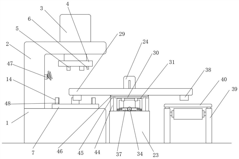
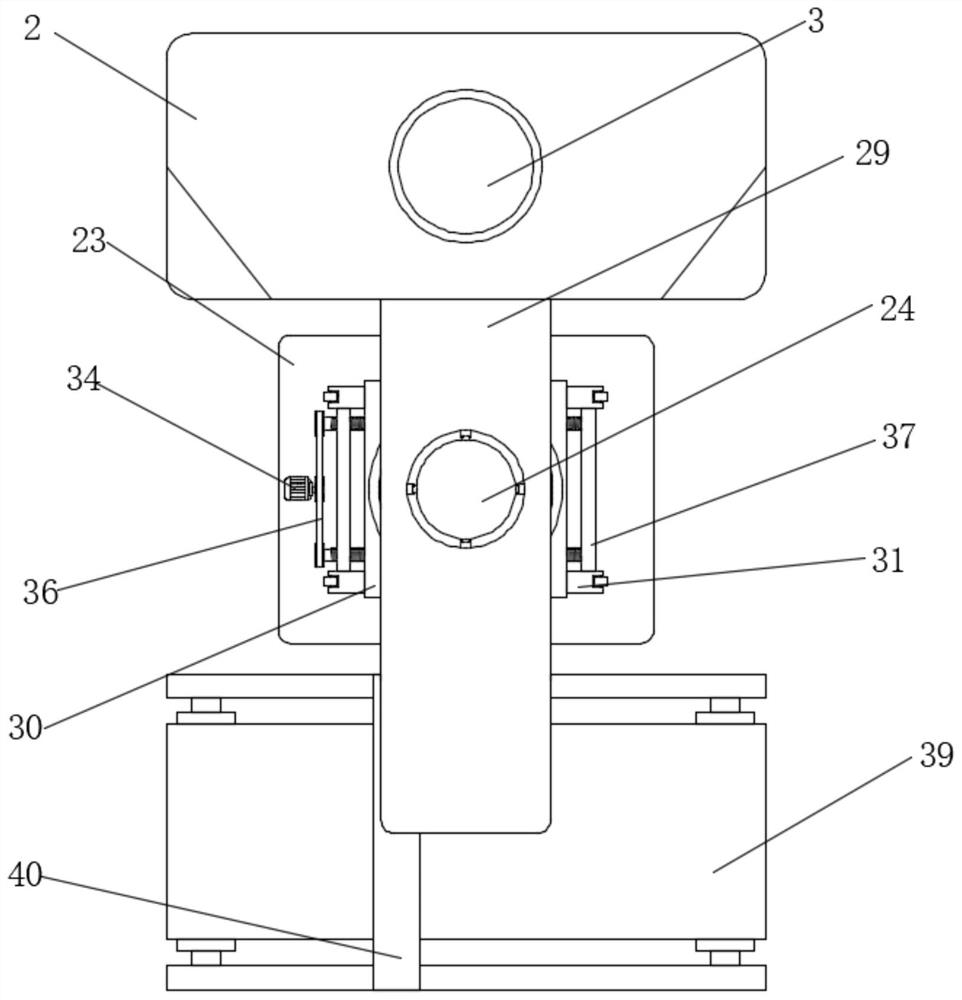
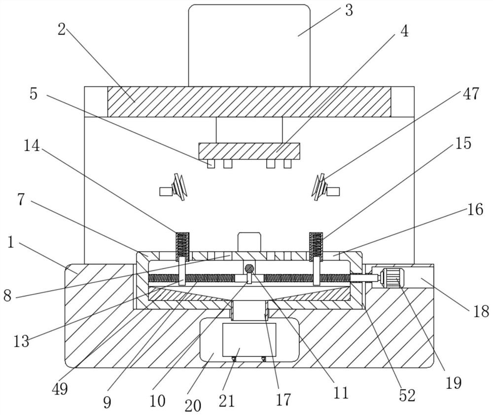
[0048] refer to Figure 1-12 , a progressive stamping system for a multi-functional electrical instrument, comprising a workbench 1, an L-shaped support plate 2 is fixedly connected to the top of the workbench 1, and a hydraulic cylinder 3 is fixedly connected to the top of the L-shaped support plate 2. The piston rod of the cylinder 3 runs through the L-shaped support plate 2 and is fixedly connected with the upper stamping plate 4. The bottom of the upper stamping plate 4 is equidistantly arranged with a plurality of stamping heads 5, and the bottom of the upper stamping plate 4 is fixedly connected with a folding plate 6. , the top of the workbench 1 is provided with a groove 52, the bottom inner wall of the groove 52 is fixedly connected with the lower stamping plate 7, the lower stamping plate 7 is provided with a clamping assembly for clamping the workpiece, and the workbench 1 is provided with a rectangular groove 20, the top inner wall of the rectangular groove 20 is p...

Embodiment 2

[0063] Embodiment two: if Figure 13 As shown in -15, a progressive stamping system for a multi-functional power meter, the difference between this embodiment and Embodiment 1 is that two symmetrical rotating plates 41 are rotatably connected to the two ends of the baffle plate 40, and the conveying Both sides of the top of the band 39 are fixedly connected with fixed blocks 51, and the two fixed blocks 51 are rotatably connected with electric retractable rods 42. The side away from the electric retractable rod 42 is slidingly connected with the rotating plate 41, and the rotation of the rotating plate 41 can be controlled by the fixed block 51, so that the stamped workpieces can fall on the rotating plate 41, which is convenient for collecting the stamped workpieces .

[0064] However, as those skilled in the art know, the working principle and wiring method of the hydraulic cylinder 3, the driving motor 19, the stepper motor 34, the rotating motor 27, the electric retractio...


PUM


Abstract

The invention belongs to the technical field of electric power meter machining, in particular to a progressive stamping system for a clamping piece of a multifunctional electric power meter and a stamping process thereof, and provides the following scheme. The progressive stamping system comprises a workbench, an L-shaped supporting plate is fixedly connected to the top of the workbench, and a hydraulic cylinder is fixedly connected to the top of the L-shaped supporting plate; and a piston rod of the hydraulic cylinder penetrates through the L-shaped supporting plate and is fixedly connected with an upper stamping plate, and a plurality of stamping heads are distributed at the bottom of the upper stamping plate at equal intervals. The stamping system is simple in structure and convenient to operate, a driving motor is started to drive a first bidirectional lead screw and a second bidirectional lead screw to rotate, then clamping blocks can be driven to move, a workpiece is fixed, the workpiece is prevented from moving during stamping, a collecting box is arranged in the workbench so that leftover materials can be recycled conveniently, in addition, manual operation is not needed in the feeding and discharging process, the probability of production accidents is reduced, and the machining efficiency can be improved.

Description

technical field [0001] The invention relates to the technical field of electric meter processing, in particular to a progressive stamping system and a stamping process for a multifunctional electric meter. Background technique [0002] Three-phase multifunctional power meter is a multifunctional intelligent meter with programmable measurement, display, digital communication and power pulse transmission output. It can complete power measurement, power metering, data display, collection and transmission, and can be widely used in substation automation. , distribution automation, intelligent building, electric energy measurement, management and assessment within the enterprise. The measurement accuracy is 0.5 grade, realize LED on-site display and remote RS-485 digital interface communication, adopt MODBUS-RTU communication protocol. [0003] However, in the prior art, since the staff needs to manually place the parts to be stamped under the stamping head for stamping during t...

Claims


Application Information

Patent Timeline
Patent Type & Authority Applications(China)
IPC IPC(8): B21D35/00B21D43/00B21D43/02B21D43/12B21D43/18B21D43/20
CPCB21D35/002B21D43/003B21D43/026B21D43/12B21D43/18B21D43/20Y02P70/10
Inventor 操国锋蒋鸿全
Owner 中电装备山东电子有限公司
Why Eureka
Try Eureka