Positioning drilling machine

A drilling machine and chassis technology, applied in boring/drilling, drilling/drilling equipment, parts of boring machine/drilling machine, etc., can solve the problems of inaccurate positioning and low processing accuracy, and improve accuracy , improve accuracy, increase resistance effect

Inactive Publication Date: 2021-05-28
董渝郸
View PDF0 Cites 0 Cited by
  • Summary
  • Abstract
  • Description
  • Claims
  • Application Information

AI Technical Summary

Problems solved by technology

[0004] Aiming at the deficiencies of the prior art, the present invention provides a positioning drilling machine, which solves the problem that the drilling machine has a simple structure, relatively low machining accuracy, and inaccurate positioning when drilling building materials

Method used


Image

  • Positioning drilling machine
  • Positioning drilling machine
  • Positioning drilling machine

Examples


Embodiment 1

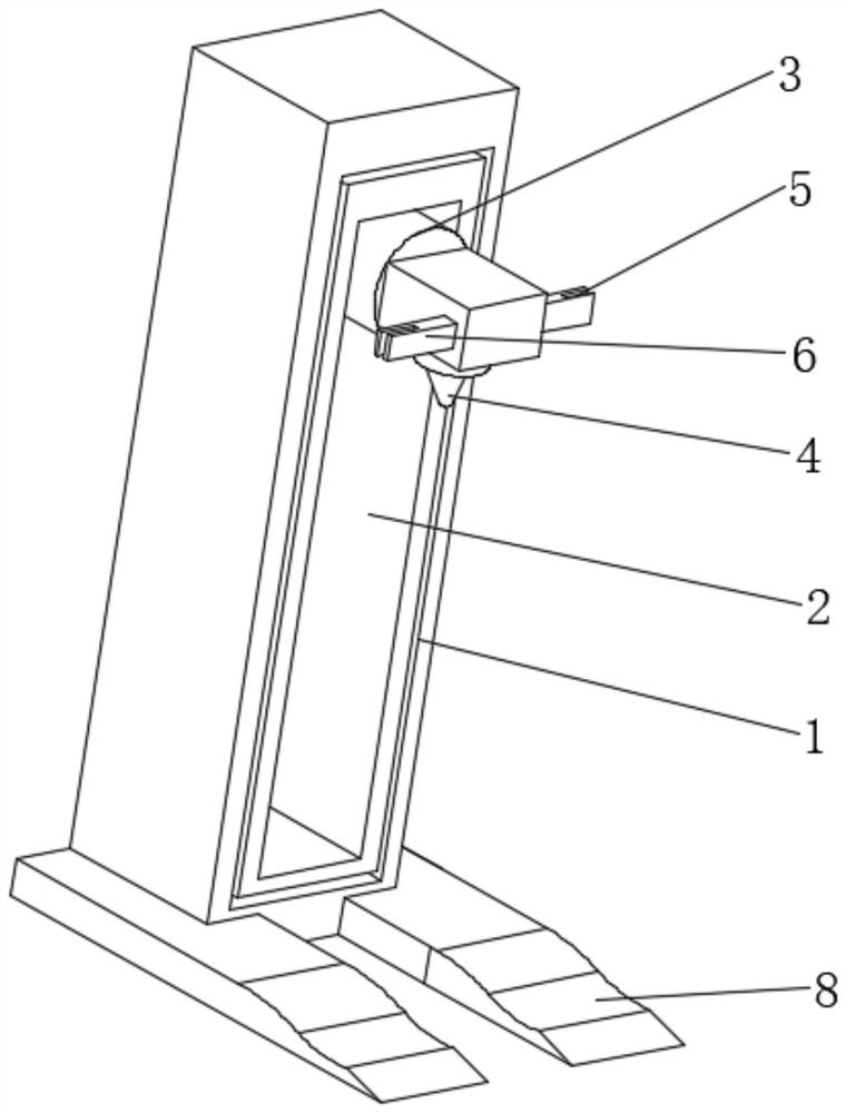
[0029] see figure 1 , the present invention provides a technical solution: a positioning drilling machine, including a chassis 1, the outer surface of the chassis 1 is provided with a sliding groove 2, the inner surface of the sliding groove 2 is slidably connected with a sliding base 3, and the outer surface of the sliding base 3 The drilling head 4 is fixedly connected through the connection block, the left and right sides of the connection block are fixedly connected with the brake plate 5, the outer surface of the brake plate 5 is provided with a U-shaped groove 6, and the inner surface of the U-shaped groove 6 is provided with a touch Mechanism 7, the bottom of the cabinet 1 is fixedly connected with a fixed plate 8, the outer surface of the fixed plate 8 is provided with a bar-shaped groove 9 directly in front of the cabinet 1, and the left and right sides of the inner surface of the bar-shaped groove 9 are provided with dark grooves 10 The inner surface of the dark groo...

Embodiment 2

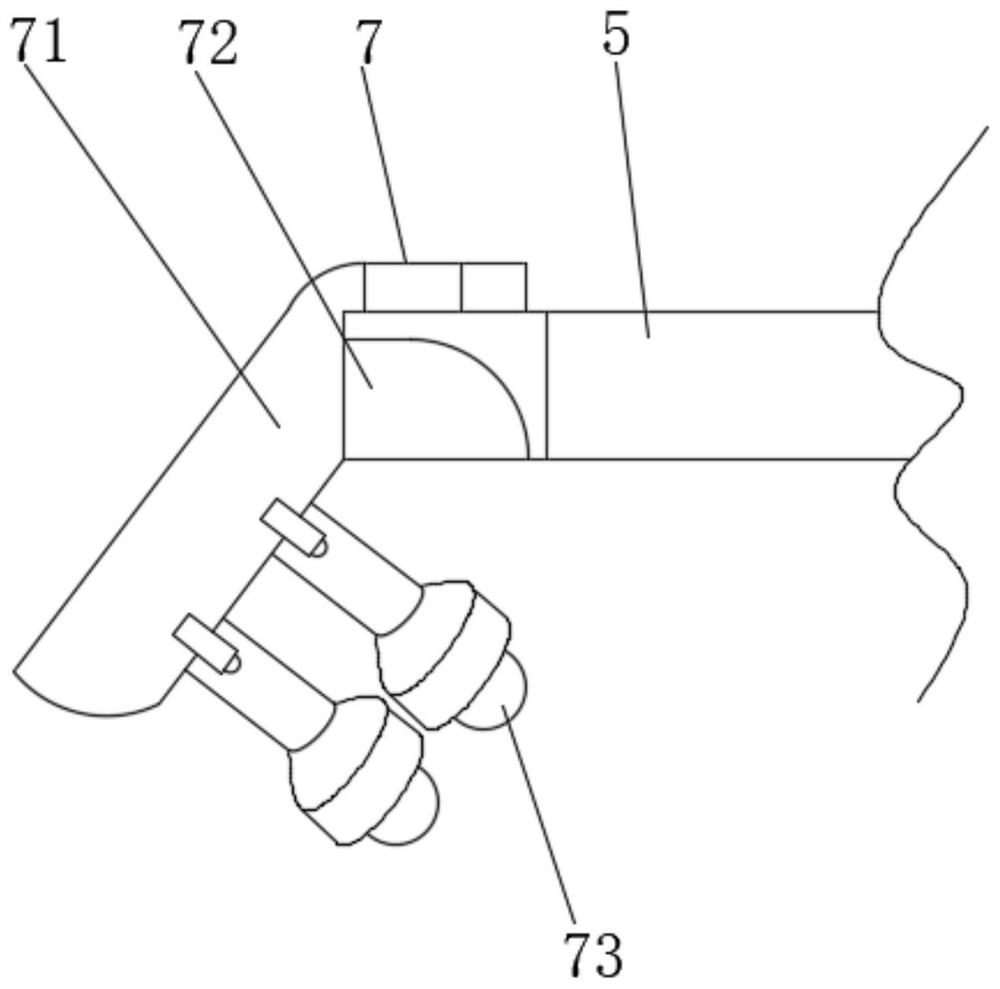
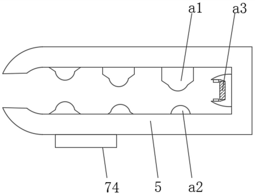
[0031] see Figure 2-3 , the present invention provides a technical solution: the trigger mechanism 7 includes a rotating curved rod 71, the outer surface of the rotating curved rod 71 is rotationally connected with the inner surface of the U-shaped groove 6, and the outer surface of the braking plate 5 is slidably connected with an arc-shaped block 72 , the rear of the arc-shaped block 72 is slidingly connected with the outer surface of the rotating curved rod 71 through the connecting rod, the bottom of the outer surface of the rotating curved rod 71 is fixedly connected with a knocking rod 73 through a spring rod, and the inner surface of the U-shaped groove 6 is provided with an anti-skid Component 74. After the arc-shaped block 72 is pushed, the arc-shaped block 72 moves upwards to leave the inside of the rotating curved rod 71, the rotating curved rod 71 rotates downward with gravity, the knocking rod 73 moves downward, and the trigger mechanism 7 can touch the positioni...

Embodiment 3

[0035] see Figure 4-6 , the present invention provides a technical solution: the positioning mechanism 11 includes an arc-shaped fixed frame 111, the left and right sides of the outer surface of the arc-shaped fixed frame 111 are respectively fixedly connected with the left and right sides of the inner surface of the strip groove 9, and the inner surface of the dark groove 10 The surface is slidingly connected with a positioning plate 112, the outer surface of the positioning plate 112 is uniformly provided with a circular groove 113, the inner surface of the circular groove 113 is fixedly connected with a positioning belt assembly 114, the outer surface of the positioning plate 112 and the inner surface of the arc-shaped fixed frame 111 Slidingly connected, the left and right sides of the top of the fixed plate 8 are all slidably connected with sliding blocks 115 . After the sliding block moves backward, the positioning plate 112 moves forward to the arc-shaped fixed frame 1...


PUM


Abstract

The invention discloses a positioning drilling machine, and relates to the technical field of buildings. The positioning drilling machine comprises a machine box, a sliding groove is formed in the outer surface of the machine box, a sliding base is slidably connected to the inner surface of the sliding groove, a drilling head is fixedly connected to the outer surface of the sliding base through a connecting block, brake plates are fixedly connected to the left side and the right side of the connecting block, and U-shaped grooves are formed in the outer surfaces of the brake plates. The sliding groove is formed in the outer portion of the machine box, the sliding base can drive the drilling head to move up and down, a drilling position can be printed on the outer surface of a workpiece through a positioning mechanism before drilling, then the positioning mechanism is driven by a touch mechanism to leave the outer surface of the workpiece, drilling is conducted along the marked position, two mechanisms are additionally arranged outside the machine, the drilling position of the workpiece can be determined more conveniently, the situation that the drilling position is not accurate enough due to manual position marking by workers is avoided, and the drilling accuracy is greatly improved.

Description

technical field [0001] The invention relates to the technical field of construction, in particular to a positioning drilling machine. Background technique [0002] Drilling refers to the operation of machining a hole in a solid material with a drill. Here is a description of the drilling work in the exploration work, as well as the auxiliary tools needed for drilling and some emergency measures. In geological exploration work, drilling equipment is used to drill a columnar hole with a small diameter and a large depth underground, also known as drilling. Boreholes for oil and gas and groundwater are larger in diameter. The diameter and depth of the drill hole depend on the burial depth of geological minerals and the purpose of the drill hole. The drilling device is used to process holes on solid materials. Common drilling devices include electric drills, drilling machines, etc. With the further development of the processing technology, the efficiency of the drilling device...

Claims


Application Information

Patent Timeline
IPC IPC(8): B23B39/00B23B47/00B25H7/04
CPCB23B39/00B23B47/00B25H7/04
Inventor 董渝郸
Owner 董渝郸
Why Eureka
Try Eureka