A lightweight, high-power, particle-rich propellant ignition device

An ignition device, high-power technology, applied in rocket engine devices, jet propulsion devices, machines/engines, etc., can solve the problems of high cost, poor ignition ability, complex design and production, and achieve weight reduction, increase effectiveness and The effect of improving reliability and quality ratio

Active Publication Date: 2022-05-10
XIAN AEROSPACE PROPULSION INST +1
View PDF0 Cites 0 Cited by
  • Summary
  • Abstract
  • Description
  • Claims
  • Application Information

AI Technical Summary

Problems solved by technology

[0005] Among them, the existing spontaneous combustion liquid ignition device and torch ignition device all have the problems of complicated design and manufacture and high cost
[0006] However, due to the large mass of the existing solid powder ignition device, and the lack of ignition particles contained in it, the ignition ability is poor. After ignition, the shell of the ignition device will fall off and damage the thrust chamber. At the same time, its structure is relatively complicated, and the cost of development and testing is relatively high.

Method used


Image

  • A lightweight, high-power, particle-rich propellant ignition device
  • A lightweight, high-power, particle-rich propellant ignition device

Examples


Embodiment 1

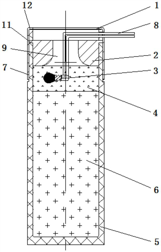
[0037] figure 1 A structure of an ignition device is disclosed, including an ignition head 3 (including an ignition lead 8), an initial charge 4, a main charge 6, a casing, a nozzle 2 and a sealing diaphragm 1;

[0038] One end of the shell is an ignition port, and a sealing diaphragm 1 is installed at the ignition port;

[0039] A nozzle 2, an initial charge 4 and a main charge 6 are sequentially arranged in the shell from the ignition port inward;

[0040] The ignition head 3 is arranged inside the starting charge 4, and its ignition lead wire 8 is drawn out of the shell;

[0041] The nozzle pipe 2 is provided with a nozzle hole 9 along the center; the diameter of the nozzle hole 9 gradually increases from the ignition port to the inside. The method in this embodiment is to form a straight hole near the nozzle hole of the sealing diaphragm, and the nozzle hole near the initial charge is trumpet-shaped, and the largest end of the trumpet shape is close to the described prim...

Embodiment 2

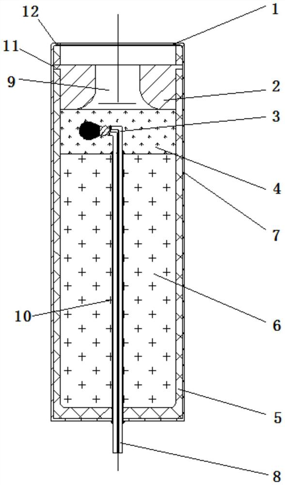
[0050] figure 2 The structure of another ignition device is disclosed, including an ignition head 3 (including an ignition lead 8), an initial charge 4, a main charge 6, a shell, a nozzle 2 and a sealing diaphragm 1;

[0051] One end of the shell is an ignition port, and a sealing diaphragm 1 is installed at the ignition port;

[0052] A nozzle 2, an initial charge 4 and a main charge 6 are sequentially arranged in the shell from the ignition port inward;

[0053] The ignition head 3 is arranged inside the starting charge 4, and its ignition lead wire 8 is drawn out of the shell;

[0054] The nozzle pipe 2 is provided with a nozzle hole 9 along the center; the diameter of the nozzle hole 9 gradually increases from the ignition port to the inside. The method in this embodiment is to form a straight hole near the nozzle hole of the sealing diaphragm, and the nozzle hole near the initial charge is trumpet-shaped, and the largest end of the trumpet shape is close to the initial...


PUM


Abstract

The invention discloses a light-weight, high-power, and particle-rich propellant ignition device, which solves the problems of high development and test costs of the existing ignition device, long development period, and easy damage to the thrust chamber caused by the remains of the ignition device after ignition. The ignition device mainly includes an ignition head, an initial charge, a main charge, a shell, a nozzle and a sealing diaphragm. After the ignition head of the ignition device is energized and detonated, the initial charge is ignited, and then the main charge is ignited. The high-temperature gas generated breaks through the sealing diaphragm through the nozzle to produce a continuous and stable flame output rich in hot particles, thereby realizing the engine. Ignition of thrust chamber propellant.

Description

technical field [0001] The invention relates to a propellant ignition device for a non-spontaneous combustion bicomponent propellant rocket engine, especially a propellant ignition device based on light weight, high power and rich particles, which can be used for non-spontaneous combustion bicomponent propellant Agent rocket engine ignition technology field. Background technique [0002] As a non-toxic and non-polluting propellant combination for launch vehicles, liquid oxygen kerosene has the characteristics of high specific impulse performance, low cost, and convenient use and maintenance, and has been widely used in the new generation of launch vehicles. The liquid oxygen kerosene bicomponent propellant is a non-spontaneous propellant, which needs to provide an initial ignition heat source to make it ignite and burn, and then rely on the heat released by its own combustion to maintain the combustion process of the propellant. [0003] Liquid rocket motors using non-pyrop...

Claims


Application Information

Patent Timeline
Patent Type & Authority Patents(China)
IPC IPC(8): F02K9/95F02K9/08
CPCF02K9/95F02K9/08
Inventor 李应强刘上杨安民王元和高凤川张建刚刘铭李永锋常鹏高耸松
Owner XIAN AEROSPACE PROPULSION INST
Why Eureka
Try Eureka