Waste gas heat energy recycling device for centralized treatment of kitchen waste

A centralized treatment and kitchen waste technology, applied in incinerators, lighting and heating equipment, combustion methods, etc., can solve the problems of resource waste, limited service life, high management requirements, etc., and achieve the convenience of next use and return Effect

Pending Publication Date: 2021-05-28
SUZHOU POLYTECHNIC INST OF AGRI
View PDF9 Cites 0 Cited by
  • Summary
  • Abstract
  • Description
  • Claims
  • Application Information

AI Technical Summary

Problems solved by technology

Chinese cities produce no less than 60 million tons of food waste every year, but most of the food waste has become a potential source of danger affecting food safety and ecological security due to improper disposal methods
[0003] For the treatment of food waste, the commonly used sanitary landfill technology has the largest treatment capacity, relatively low operating costs, relatively simple process, and low investment. It is the final digestion method for residues generated by other treatment methods, but the treatment address of this method is limited. , occupies a large area, has a limited service life, high management requirements, and water and air pollution cannot be completely solved; the incineration method has a high degree of reduction, the calorific value of garbage can be used, the ground is highly harmless, and the land occupation is small, and the capacity reduction is relatively large. Large, but this method requires large investment, high operating costs, large water content of kitchen waste, low calorific value, easy to cause incineration d

Method used


Image

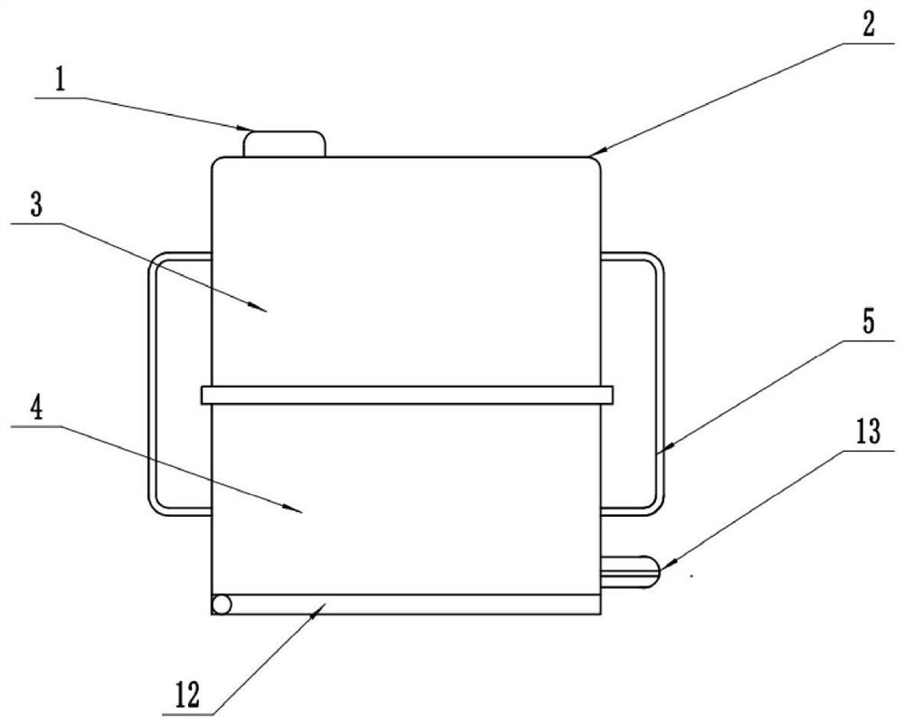
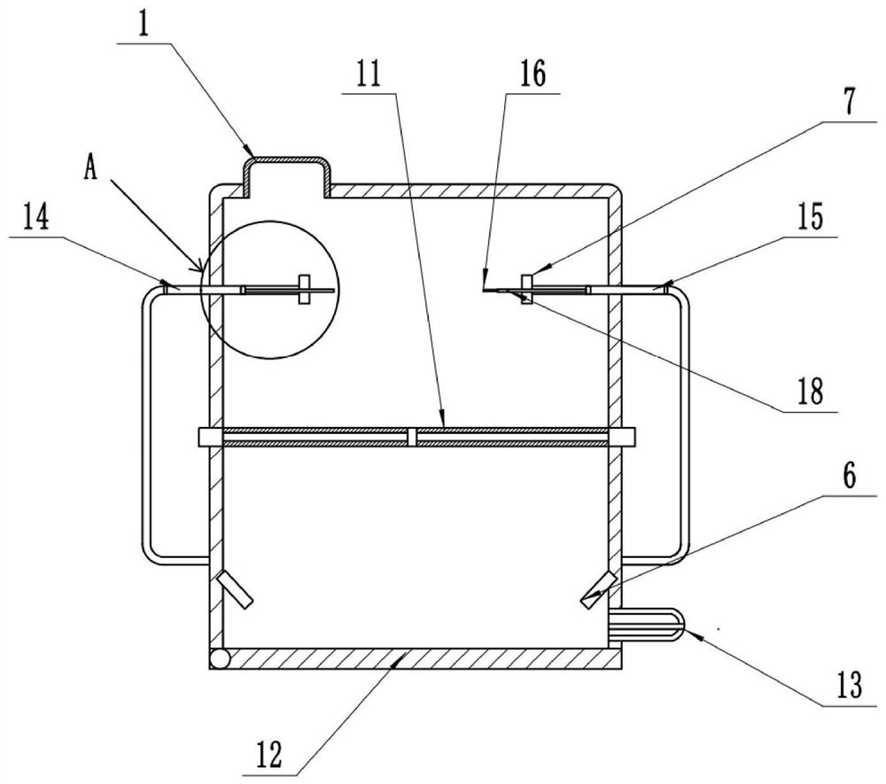
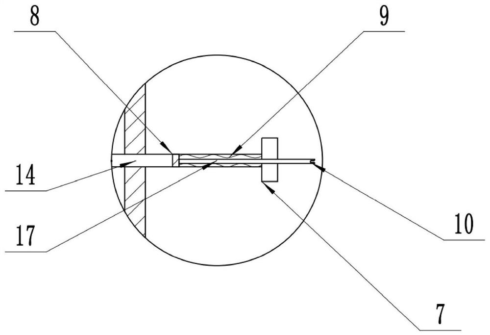
  • Waste gas heat energy recycling device for centralized treatment of kitchen waste
  • Waste gas heat energy recycling device for centralized treatment of kitchen waste
  • Waste gas heat energy recycling device for centralized treatment of kitchen waste

Examples


Embodiment Construction

[0025]Embodiments of the present invention will be described in detail below, and examples of the embodiments are illustrated in the drawings, in which the same or similar reference numerals represent the same or similar elements or elements having the same or similar functions. The following is exemplary, and is intended to be used herein, not to be construed as limiting the invention.

[0026]In the description of the invention, it is to be understood that the term "longitudinal", "horizontal", "vertical", "upper", "lower", "front", "left", "right", The orientation relationship between "vertical", "horizontal", "top", "bottom", "inside", "outside", etc. is based on the orientation or positional relationship shown in the drawings, is only for convenience of description And simplifying the description, rather than indicating or implying that the device or element must have a specific orientation, constructed and operated in a particular orientation, and thus is not to be construed as l...


PUM

PropertyMeasurementUnit
Boiling pointaaaaaaaaaa

Abstract

The invention discloses a waste gas heat energy recycling device for centralized treatment of kitchen waste in the field of waste treatment and aims to increase the utilization rate of waste gas heat energy in the kitchen waste combustion process. In order to achieve the purpose, the waste gas heat energy recycling device for centralized treatment of kitchen waste comprises an incinerator with an inlet and an outlet; the incinerator is provided with a drying layer and an incineration layer in sequence from an inlet to an outlet; a heat conduction pipe is communicated between the bottom of the incineration layer and the drying layer; and the junction of the heat conduction pipe and the drying layer communicates with a heat energy utilization device. According to the technical scheme of the waste gas heat energy recycling device for centralized treatment of the kitchen waste, the integrated incinerator seals the drying layer and the incineration layer, so that heat of the incineration layer is transferred to the drying layer to achieve the material drying effect, the situation that wastes cannot be fully burnt due to too high water content is avoided, and waste gas heat energy utilization is achieved.

Description

Technical field[0001]The present invention belongs to the field of waste treatment, and is specifically a kitchen waste concentration treatment of exhaust gas heat energy reuse.Background technique[0002]The kitchen garbage is commonly known as the feet, also known as the water, and the water is a living waste formed by residents in the living consumption of living. It is very easy to rot, emits stink, spread bacteria and virus. The main ingredients of kitchen waste include rice and flour residues, vegetables, animal and vegetable oils, meat bones, wastebinations, plastics, paper towels, peel, and other mixed solids. From chemical composition, there is starch, cellulose, protein, lipids and inorganic salts. The main feature of the kitchen garbage is rich in organic matter, high moisture content, easy to rot, its storage time is slightly longer, mites, cockroaches, increase the kitchen odor, its traits and odors will cause harsh impact on environmental health, affect residents' health...

Claims


Application Information

Patent Timeline
IPC IPC(8): F23G5/04F23G5/08F23G5/44F23G5/46
CPCF23G5/04F23G5/08F23G5/44F23G5/46F23G2201/10F23G2201/20F23G2204/10F23G2206/10
Inventor 杨伟球
Owner SUZHOU POLYTECHNIC INST OF AGRI
Why Eureka
Try Eureka